Automatic conducting strip welding device and machining technology thereof

A technology of automatic welding and welding equipment, which is applied in the field of electronic product preparation process equipment, can solve the problems of wasting manpower and limiting production speed, etc.

Inactive Publication Date: 2016-04-13
邓泽松
View PDF9 Cites 1 Cited by
  • Summary
  • Abstract
  • Description
  • Claims
  • Application Information

AI Technical Summary

Problems solved by technology

The device needs to manually prevent the conductive sheet from bending on th

Method used


Image

  • Automatic conducting strip welding device and machining technology thereof
  • Automatic conducting strip welding device and machining technology thereof
  • Automatic conducting strip welding device and machining technology thereof

Examples


Embodiment 1

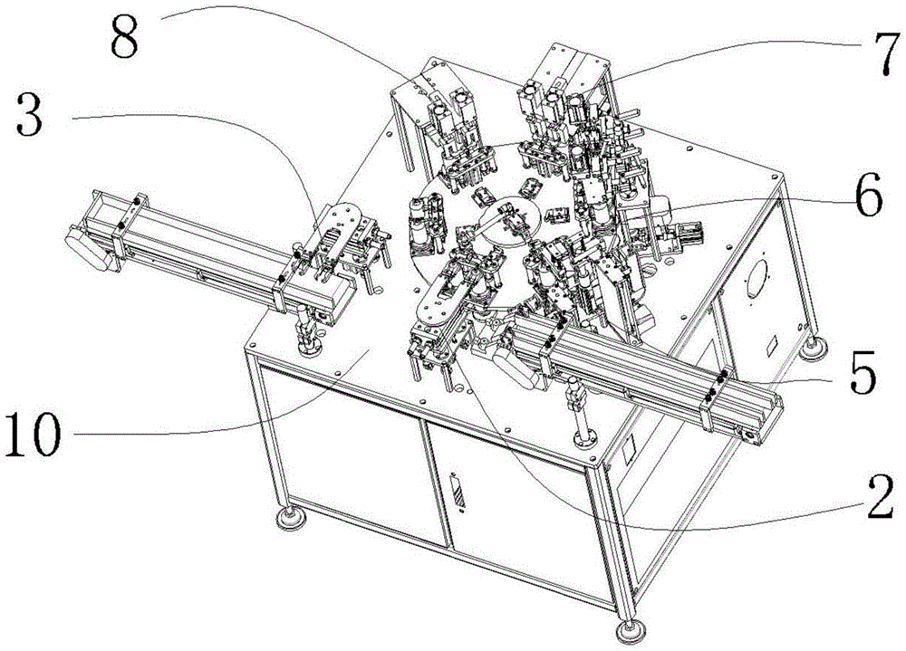
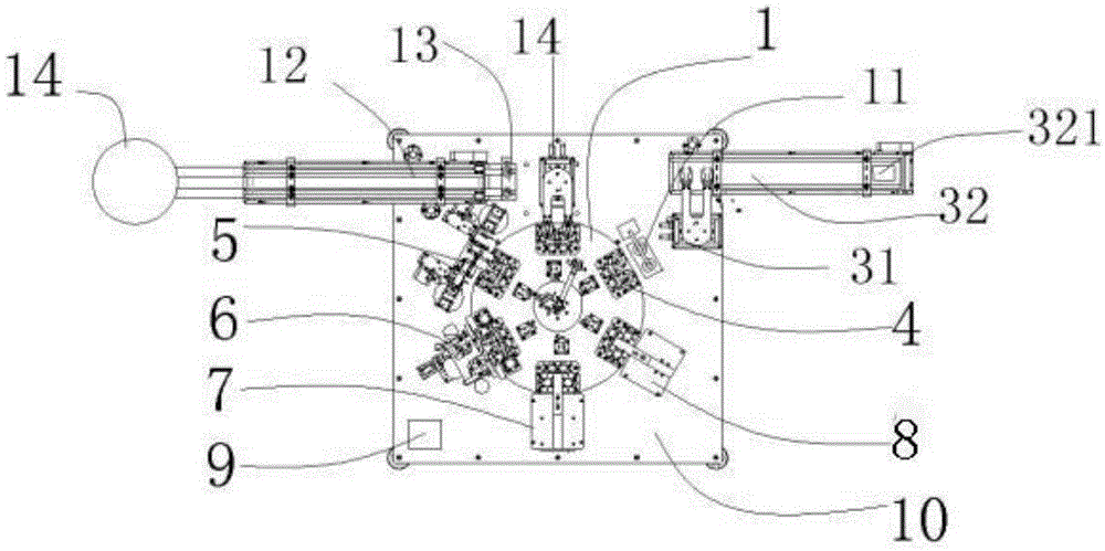
[0039] As shown in the figure, the battery conductive sheet welding and bending device includes a workbench on which a turntable 1, a feeding device 2 and a discharging device 3 are installed. The feeding device 1 includes a clamping device 14 and a conveyor belt 1. 12. A tray 13 is provided at the end of the conveyor belt one 12, and the discharge device 3 includes a clamping device two 31 and a conveyor belt two 32. It is characterized in that a grabbing device 4 is provided on the turntable, and the turntable Along the edge, a loading device 5, a welding device 6, a bending device 1 7, a bending device 2 8, a protective cover, and a monitoring device 9 are installed in sequence.

[0040] Described clamping device one 14 comprises movable plate 141, and described movable plate 141 is provided with the rotating shaft four 143 that cylinder nine 142 drives rotation, and described movable splint 141 is also provided with movable clip 144, controls movable clip by electric two 14...

Embodiment 2

[0056] As shown in the figure, the battery conductive sheet welding and bending device includes a workbench on which a turntable 1, a feeding device 2 and a discharging device 3 are installed. The feeding device 1 includes a clamping device 14 and a conveyor belt 1. 12. The end of the conveyor belt 12 is provided with a tray 13, and the discharge device 3 includes a clamping device 2 31, a conveyor belt 2 32 and a waste recycling tank 321. The waste recycling tank is used to store unqualified products that have not passed the quality inspection. Finished product; it is characterized in that a grabbing device 4 is provided on the turntable, and the turntable is sequentially installed with a sheet loading device 5, a welding device 6, a bending device 7, a bending device 2 8, a protective cover, a monitoring device9.

[0057] Described clamping device one 14 comprises movable plate 141, and described movable plate 141 is provided with the rotating shaft four 143 that cylinder ni...

Embodiment 3

[0073] As shown in the figure, the battery conductive sheet welding and bending device includes a workbench on which a turntable 1, a feeding device 2 and a discharging device 3 are installed. The feeding device 1 includes a clamping device 14 and a conveyor belt 1. 12. The end of the conveyor belt 12 is provided with a tray 13, and the discharge device 3 includes a clamping device 2 31, a conveyor belt 2 32 and a waste recycling tank 321. The waste recycling tank is used to store unqualified products that have not passed the quality inspection. The finished product is characterized in that a grabbing device 4 is provided on the turntable, and a sheet loading device 5, a welding device 6, a bending device 1 7, a bending device 2 8, a protective cover, and a monitoring device are sequentially installed along the turntable. device9.

[0074] Described clamping device one 14 comprises movable plate 141, and described movable plate 141 is provided with the rotating shaft four 143 ...


PUM


Abstract

The invention relates to electronic product manufacturing technology equipment, and particularly provides an automatic conducting strip welding device and a machining technology thereof. The automatic welding device comprises a workbench, and the workbench is provided with a rotary plate, a feeding device and a discharging device. The automatic welding device is characterized in that the rotary plate is provided with a gripping device and sequentially provided with a strip feeding device, a welding device body, a first bending device and a second bending device along the edge. By adopting the automatic welding device, a welding and bending machining technology for welding a bent battery conducting strip can be achieved, and integrated production of welding and bending can be achieved by arranging the welding device body, the first bending device and the second bending device on the workbench; meanwhile, through cooperation of the first bending device and the second bending device, the battery conducting strip can be stressed uniformly in the bending process, and the fall-off phenomenon cannot occur.

Description

technical field [0001] The invention relates to an electronic product preparation process equipment, in particular to a conductive sheet automatic welding device and its processing technology. Background technique [0002] The production process of the traditional battery conductive sheet is welding first, and then manual bending. During the bending process, due to the uneven force used each time, the bending angle of each completed conductive sheet will be different; moreover, because the manual operation is not easy to control, the previously welded conductive sheet is prone to fall off. At the same time, the manual operation is slow and the production volume is small. [0003] For example, 104384933A discloses a fully automatic bending and welding machine, which is characterized in that it includes an upper bending module, a bottom vacuum adsorption platform, and a laser module, and the bottom vacuum adsorption platform includes an adsorption panel, and the adsorption pa...

Claims


Application Information

Patent Timeline
IPC IPC(8): B23P15/00
CPCB23P15/00
Inventor 邓泽松
Owner 邓泽松
Why Eureka
Try Eureka