
Double-pressure-tank shot generation system in shot blasting device

A dual-pressure tank and generating system technology, applied in metal processing equipment, abrasives, manufacturing tools, etc., can solve the problem of unstable pellet flow, achieve the effect of ensuring pellet flow and delaying the inflation time

Inactive Publication Date: 2016-04-13
WUXI TURBINE BLADE
View PDF6 Cites 4 Cited by
  • Summary
  • Abstract
  • Description
  • Claims
  • Application Information

AI Technical Summary

Problems solved by technology

[0004] The purpose of the present invention is to provide a double-pressure tank shot generation system in shot peening equipment, which can ensure the continuous stability of the shot flow, so as to solve the problem of shot flow when the double-pressure tank shot generation system in the shot peening equipment is refueled in the prior art. unstable problem

Method used


Image

  • Double-pressure-tank shot generation system in shot blasting device

Examples


Embodiment Construction

[0014] The technical solutions of the present invention will be further described below in conjunction with the accompanying drawings and through specific implementation methods.

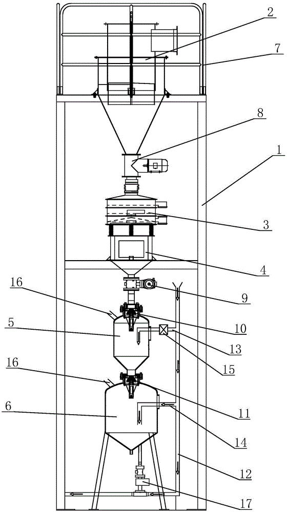
[0015] see figure 1 as shown, figure 1 It is a schematic structural view of the double-pressure tank shot generation system in the shot peening equipment provided in Embodiment 1 of the present invention.

[0016] A double-pressure tank shot generation system in shot blasting equipment includes a frame 1, on which a cyclone separator 2, a vibrating screen 3, a storage hopper 4, and an upper shot blasting tank are sequentially arranged from top to bottom and connected to each other 5 and the lower shot blast tank 6, the top of the frame 1 is provided with a guardrail 7 on the periphery of the cyclone separator 2. A blower fan 8 is set between the cyclone separator 2 and the vibrating screen 3, a feed valve 9 is set between the storage hopper 4 and the upper shot blast tank 4, and the upper part of ...


PUM


Abstract

The invention discloses a double-pressure-tank shot generation system in a shot blasting device. The double-pressure-tank shot generation system comprises a rack. The rack is sequentially provided with a cyclone separator, a vibrating screen, a storage hopper, an upper shot blasting tank and a lower shot blasting tank from top to bottom. An air closing machine is arranged between the cyclone separator and the vibrating screen. A feeding valve is arranged between the storage hopper and the upper shot blasting tank. A first sealing valve is arranged on the upper portion of the upper shot blasting tank. A second sealing valve is arranged on the upper portion of the lower shot blasting tank. The rack is further provided with a main gas supply pipeline. The main gas supply pipeline is communicated with the upper shot blasting tank and the lower shot blasting tank through an upper branch gas supply way and a lower branch gas supply way. A control valve is installed on the upper branch gas supply way. Air outlets are formed in the upper shot blasting tank and the lower shot blasting tank. According to the double-pressure-tank shot generation system in the shot blasting device, it can be ensured that shot blasting gas is not affected by the process of material changing of the upper shot blasting tank or the lower shot blasting tank, and continuity and stability of shot flow are ensured.

Description

technical field [0001] The invention relates to a shot peening equipment, in particular to a double pressure tank shot generating system in the shot peening equipment. Background technique [0002] Pneumatic shot peening equipment adopts double pressure tanks to realize continuous shot peening. The shot material of the pneumatic shot peening equipment is stored in the shot peening tank. When the shot peening operation is performed, the combined valve on the shot peening tank moves to lift the sealing valve on the shot peening tank and pressurize the shot blasting tank. At the same time, the shot valve under the shot blast tank is opened, and the booster valve is opened; like this, because the shot blast tank has been pressurized, the shot material enters the discharge port from the feed port of the shot valve The shot material at the feed port is accelerated; the accelerated shot air mixed flow passes through the shot blasting tube to the spray gun, and the shot material is...

Claims


Application Information

Patent Timeline
IPC IPC(8): B24C7/00
CPCB24C7/00B24C7/0061
Inventor 徐鲲濠魏德成滕树新王烜烽汤先辉史奎
Owner WUXI TURBINE BLADE
Learn More