Follow-up saw blade guard

A saw blade cover and follow-up technology, which is applied to metal processing machinery parts, maintenance and safety accessories, work accessories, etc., can solve the problems of high cost, high material consumption and heavy shape of the saw blade cover, and improve the device Long service life, improved operating comfort, and low production and processing costs

Active Publication Date: 2017-08-15
BOSUN TOOLS CO LTD
View PDF6 Cites 0 Cited by
  • Summary
  • Abstract
  • Description
  • Claims
  • Application Information

AI Technical Summary

Problems solved by technology

The saw blade cover has the following deficiencies during use: first, the saw blade cover is bulky and heavy, making it extremely inconvenient to store, transport, and install; Failure to discharge in time not only deteriorates the construction environment, but also affects the construction effect; the third is that the saw blade cover uses a lot of materials, the process is complicated, the production process is numerous, and the cost is high
In view of the above situation, many domestic users do not use saw blade covers at all in most cases, and there are great potential safety hazards

Method used


Image

  • Follow-up saw blade guard
  • Follow-up saw blade guard
  • Follow-up saw blade guard

Examples


Embodiment 1

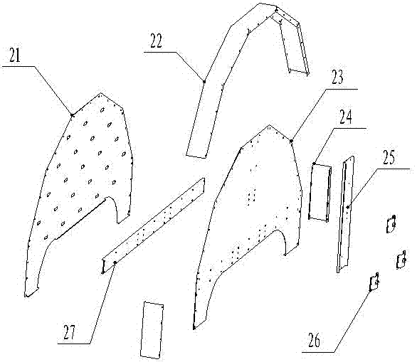
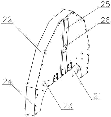
[0030] Such as figure 1 and figure 2 As shown, a follow-up saw blade cover includes a rear cover 21, a front cover 23 opposite to the rear cover 21 and separated by a cavity for covering the saw blade, and connected to the top of the rear cover 21 and the front cover 23. The top plate 22, the side plate 24 connected to the side ends of the rear cover 21 and the front cover 23 and connected to the bottom of the top plate 22, the reinforcement rib II 25 vertically fixed on the outside of the front cover 23, and the reinforcement rib II 25 horizontally fixed on the inside of the front cover 23 I27. Three supporting and fixing plates 26 arranged on the front cover 23.

[0031] Rear cover 21 and front cover 23 as figure 1 and figure 2 As shown, including the main structure and the connecting part, the main structures of the rear cover 21 and the front cover 23 are all shapes after a part is cut by a circular horizontal knife, but the upper edges of the two are not smooth arc l...

Embodiment 2

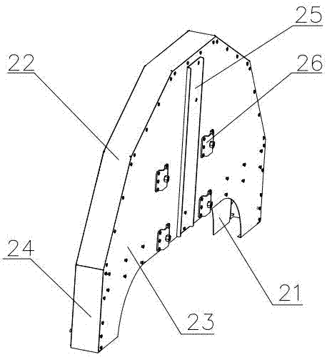
[0036] The difference between this embodiment and embodiment 1 is: see image 3 , there are four supporting and fixing plates 26, which are evenly arranged at the lower part of the front cover 23, and of course can also be evenly arranged at the middle part of the front cover 23; to the settings.

Embodiment 3

[0038] The difference between this embodiment and embodiment 1 is: see Figure 4 and Figure 5 , is also provided with a folding water retaining mechanism, and the folding water retaining mechanism includes two L-shaped fixed plates 4 fixed on the bottom of the rear cover 21 and the front cover 23 by riveting the head end respectively, and two L-shaped fixed plates 4. The two-stage water retaining piece made of channel steel is movably connected at the tail end. There are three riveting holes on the fixed plate 4, and the three riveting holes are arranged in a triangle; The tail end of the fixed plate 4, the head end of the second level water retaining sheet is movably connected to the tail end of the first stage water retaining sheet, the first stage water retaining sheet 1 is slightly wider than the board part of the second stage water retaining sheet 2, install Put the head end of the second-stage water retainer 2 into the tail end of the first-stage water retainer 1, and ...


PUM


Abstract

The invention discloses a slave type saw blade cover, and belongs to the technical field of wall saw cutting and protecting devices. The slave type saw blade cover comprises a rear cover, a front cover, a top plate, side plates, a reinforcing rib II, a reinforcing rib I and more than three supporting and fixing plates, wherein the top plate is connected to the tops of the rear cover and the front cover; the side plates are connected with the side ends of the rear cover and the front cover and are connected with the bottom of the top plate; the reinforcing rib II is vertically fixed on the outer side of the front cover; the reinforcing rib I is laterally fixed on the inner side of the front cover; the supporting and fixing plates are arranged on the front cover; the lower ends of the rear cover and the front cover are opened; the supporting and fixing plates adopt arc-shaped plates protruding outwards; set bolts are arranged on the supporting and fixing plates; one of the supporting and fixing plates is arranged in the middle of the reinforcing rib II, and the two other supporting and fixing plates are symmetrically arranged at the bottom of the front cover along the longitudinal center line of the reinforcing rib II; a drain hole is formed in the rear cover; and the slave type saw blade cover is further provided with a folding water retaining mechanism. The slave type saw blade cover is small in size, light in weight, convenient to mount and transport, simple in production process, low in cost, and good in effect of retaining water on a concave surface, is not prone to deform, and can adjust the water retaining range arbitrarily.

Description

technical field [0001] The invention discloses a follow-up saw blade cover, which belongs to the technical field of cutting protection devices for wall saws. Background technique [0002] The saw blade cover of the wall saw generally adopts a full protective structure, the saw blade moves inside the saw blade cover, and the movement of the machine head and the saw blade cover is not synchronized. The saw blade cover has the following deficiencies during use: first, the saw blade cover is bulky and heavy, making it extremely inconvenient to store, transport, and install; Failure to discharge in time not only deteriorates the construction environment, but also affects the construction effect; the third is that the saw blade cover consumes a lot of materials, the process is complicated, the production process is various, and the cost is high. In view of the above, many domestic users do not use saw blade covers at all in most cases, and there is a great potential safety hazard...

Claims


Application Information

Patent Timeline
Patent Type & Authority Patents(China)
IPC IPC(8): B23Q11/08B28D7/00
CPCB28D7/00
Inventor 王志奇田建春任淑青李会彦
Owner BOSUN TOOLS CO LTD
Why Eureka
Try Eureka