Rear suspension structure of rear transverse passenger car frame of engine
A technology of engine and horizontal placement, which is applied in the substructure, vehicle parts, transportation and packaging, etc., which can solve the problems of weak stability under force, easily damaged rear suspension frame, and large space occupation, so as to enhance the stability under force, The effect of improving the stability of force and strong stability of force
- Summary
- Abstract
- Description
- Claims
- Application Information
AI Technical Summary
Problems solved by technology
Method used
Image

Examples
Embodiment 1
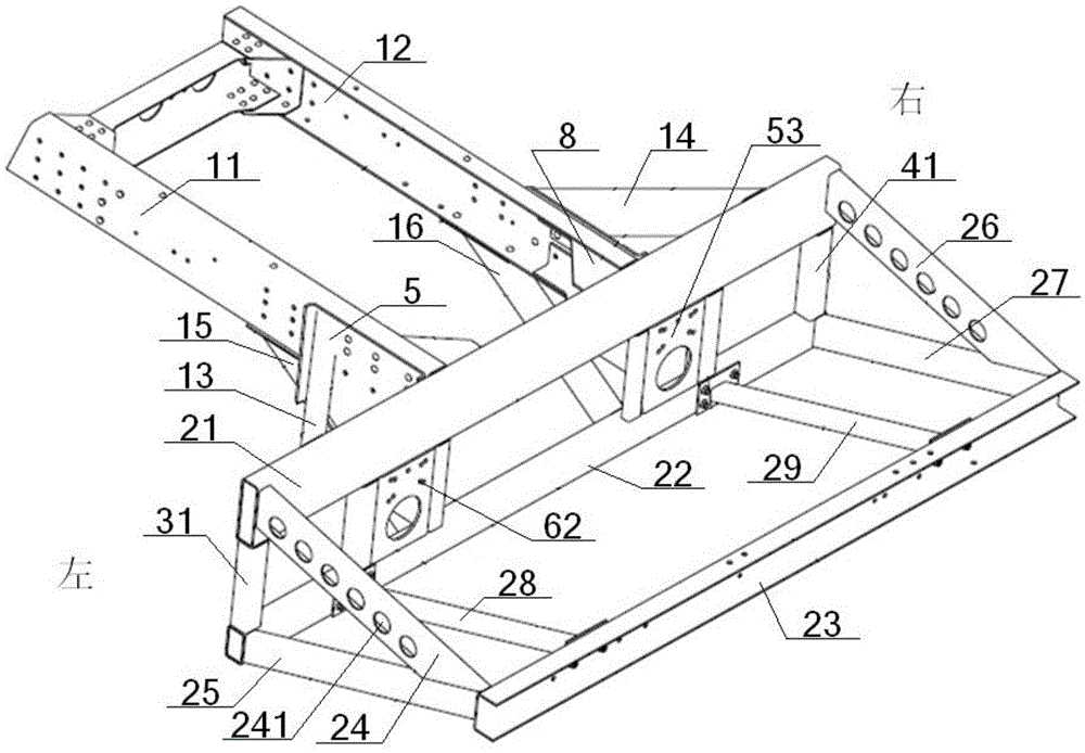
[0065] see Figure 1 to Figure 11 , a rear suspension structure of a passenger car frame with an engine rear transversely placed, comprising a rear longitudinal beam 1, a rear transverse frame 2, and a left special-shaped connecting bracket 5 and a right special-shaped connecting bracket 6 with the same structure, and the rear longitudinal beam 1 includes The left rear longitudinal beam 11 and the right rear longitudinal beam 12 are parallel to each other, and the gearbox assembly 10 and the horizontal engine assembly 9 are arranged in the rear transverse frame 2;
[0066] The rear horizontal frame 2 includes an upper beam 21, a lower beam 22, an outer beam 23, a left upper slant beam 24, a left lower slant beam 25, a right upper slant beam 26, and a right lower slant beam 27. The upper beam 21 and the lower beam 22 2. Outer crossbeams 23 are parallel to each other. The outer surface of the middle part of the upper crossbeam 21 is vertically connected with the inner ends of th...
Embodiment 2
[0069] Basic content is the same as embodiment 1, the difference is:
[0070] The middle connecting plate 52 is connected to one side of the side connecting plate 53 through an arc-shaped flange 63, and the other side of the side connecting plate 53 is provided with an outwardly expanding flange 64, and the arc-shaped flange 63 is connected to the left three vertical beams. 33 or the connection mode between the right three vertical beams 43 is welding, and the connection mode between the outward expansion flange 64 and the left two vertical beams 32 or the right two vertical beams 42 is welding. A recessed load-relief groove 65 is provided at the junction of the mesial connecting plate 52 and the side connecting plate 53 on the upper connecting plate 51; a plurality of cooling fans are provided on the left upper inclined beam 24 and the right upper inclined beam 26. ventilation holes 241 .
Embodiment 3
[0072] Basic content is the same as embodiment 1, the difference is:
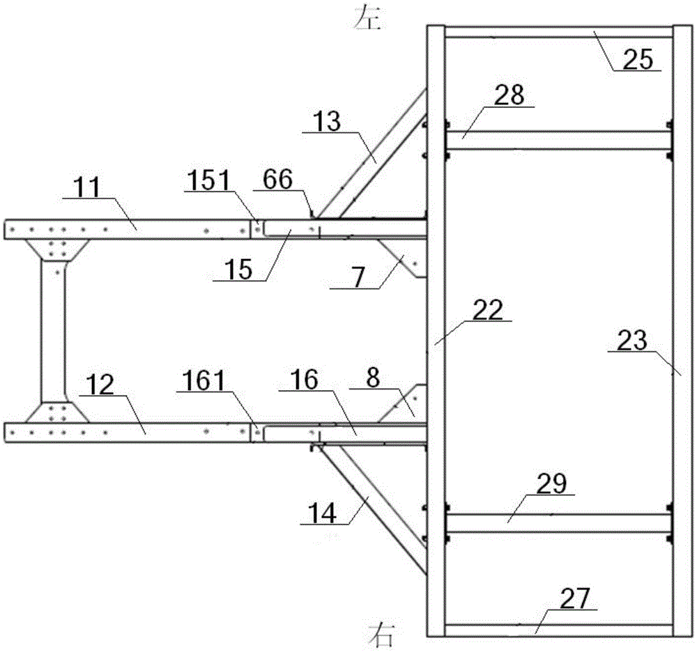
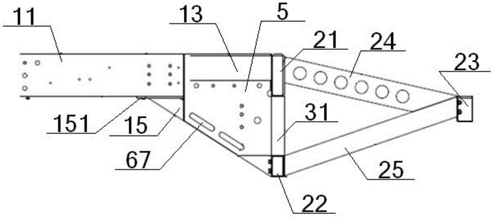
[0073] The rear suspension structure also includes the left upper connecting beam 13 and the right upper connecting beam 14 with the same structure; the side of the upper connecting plate 51 and the middle connecting plate 52 far away from the rear horizontal frame 2 and the same outwardly expanded vertical flange 66, the upper connecting plate 51 is connected to one end of the upper left connecting beam 13 or the upper right connecting beam 14 at the position between the vertical flange 66 and the longitudinal beam connecting hole 61, and the other end of the upper left connecting beam 13 or the upper right connecting beam 14 One end is connected with the outer surface of the upper beam 21 . The rear suspension structure also includes a left lower connecting beam 15 and a right lower connecting beam 16 with the same structure; one end of the left lower connecting beam 15 is connected to the bottom surface ...
PUM
 Abstract
Description
Claims
Application Information
 - R&D
- Intellectual Property
- Life Sciences
- Materials
- Tech Scout
- Unparalleled Data Quality
- Higher Quality Content
- 60% Fewer Hallucinations
Browse by: Latest US Patents, China's latest patents, Technical Efficacy Thesaurus, Application Domain, Technology Topic, Popular Technical Reports.
© 2025 PatSnap. All rights reserved.Legal|Privacy policy|Modern Slavery Act Transparency Statement|Sitemap|About US| Contact US: help@patsnap.com