Control device of ship crane
A technology of marine cranes and control devices, applied in the direction of transportation and packaging, load hanging components, etc., can solve the problems of reducing production efficiency, increasing work costs, etc., and achieve the effect of solving the problem of load swing, easy to implement, and simple and convenient in design
- Summary
- Abstract
- Description
- Claims
- Application Information
AI Technical Summary
Problems solved by technology
Method used
Image
Examples
Embodiment 1
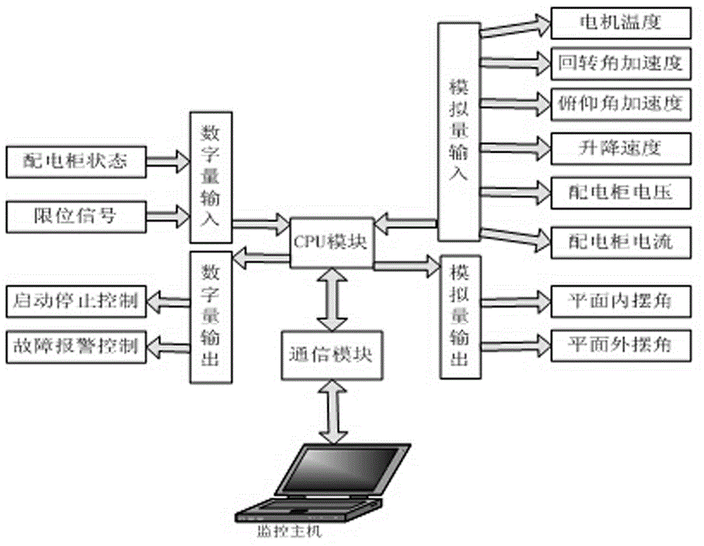
[0013] combine figure 1 , figure 1 It is a structural diagram of the PLC-based marine crane control system of the present invention, which mainly includes: CPU module, communication module, digital input, digital output, analog input, and analog output. The digital input includes the state of the power distribution cabinet, Limit signal, the digital output includes start-stop control, fault alarm control, the analog input includes motor temperature, rotation angular acceleration, pitch angular acceleration, lifting speed, power distribution cabinet voltage, power distribution cabinet current, The analog quantity output includes the in-plane swing angle and the out-of-plane swing angle; the operation process of the marine crane is divided into a slewing operation process, a pitching operation process and a lifting operation process, and the marine crane operating mechanism includes a slewing operating mechanism, a pitching operating mechanism and an elevator mechanism ; In the...
Embodiment 2
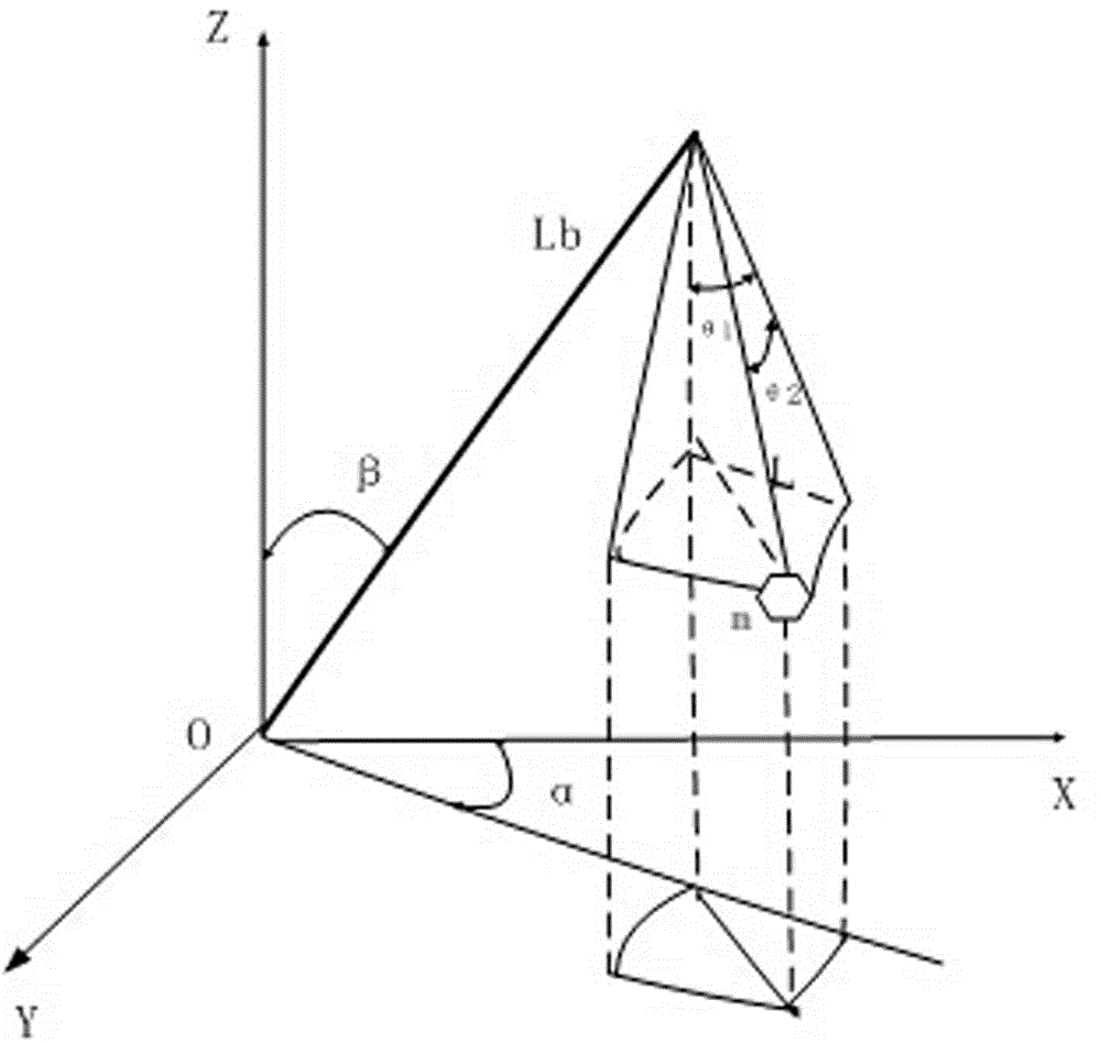
[0015] figure 2 Physical model for a marine crane. In the physical model of a marine crane, the residual swing of the load can be expressed as the swing angle in the plane of the boom and the swing angle out of the plane of the boom . Let the mass of the load be m , the length of the boom is , the rope length is L , the plane of the boom and the horizontal axis of the marine crane (ie X axis) is the rotation angle , the plane of the boom and the vertical axis of the marine crane (ie Z axis) is the pitch angle , then the position of the boom tip in the inertial coordinate system is
[0016]
[0017] The position of the load in the inertial coordinate system is
[0018]
[0019] Substituting the above formula into the position of the load in the inertial coordinate system is
[0020]
[0021] In the formula Both change over time. When considering the length of the rope, Also changes over time.
Embodiment 3
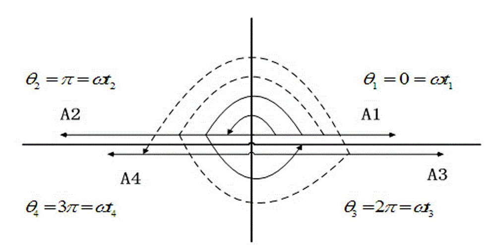
[0023] image 3 The vector diagram of the bimodal EI shaper; using the vector diagram to combine the constraint equations, the parameters for solving the bimodal EI input shaper of the undamped system are
[0024]
[0025]
[0026] in, .
PUM
 Abstract
Description
Claims
Application Information
 - R&D
- Intellectual Property
- Life Sciences
- Materials
- Tech Scout
- Unparalleled Data Quality
- Higher Quality Content
- 60% Fewer Hallucinations
Browse by: Latest US Patents, China's latest patents, Technical Efficacy Thesaurus, Application Domain, Technology Topic, Popular Technical Reports.
© 2025 PatSnap. All rights reserved.Legal|Privacy policy|Modern Slavery Act Transparency Statement|Sitemap|About US| Contact US: help@patsnap.com


