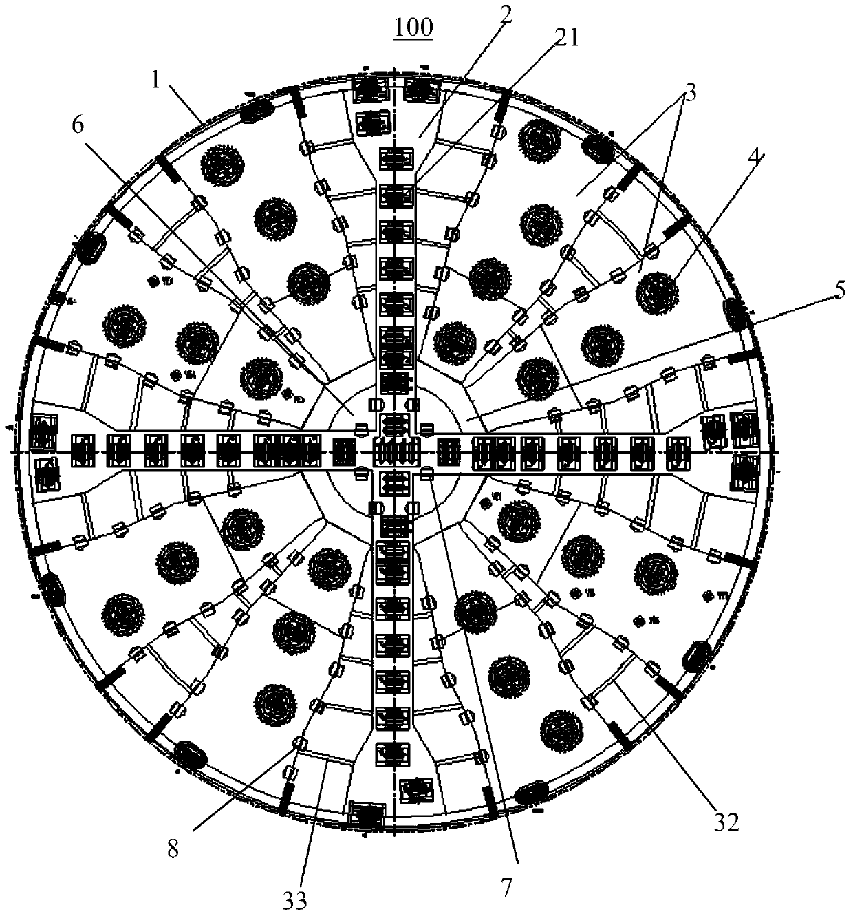
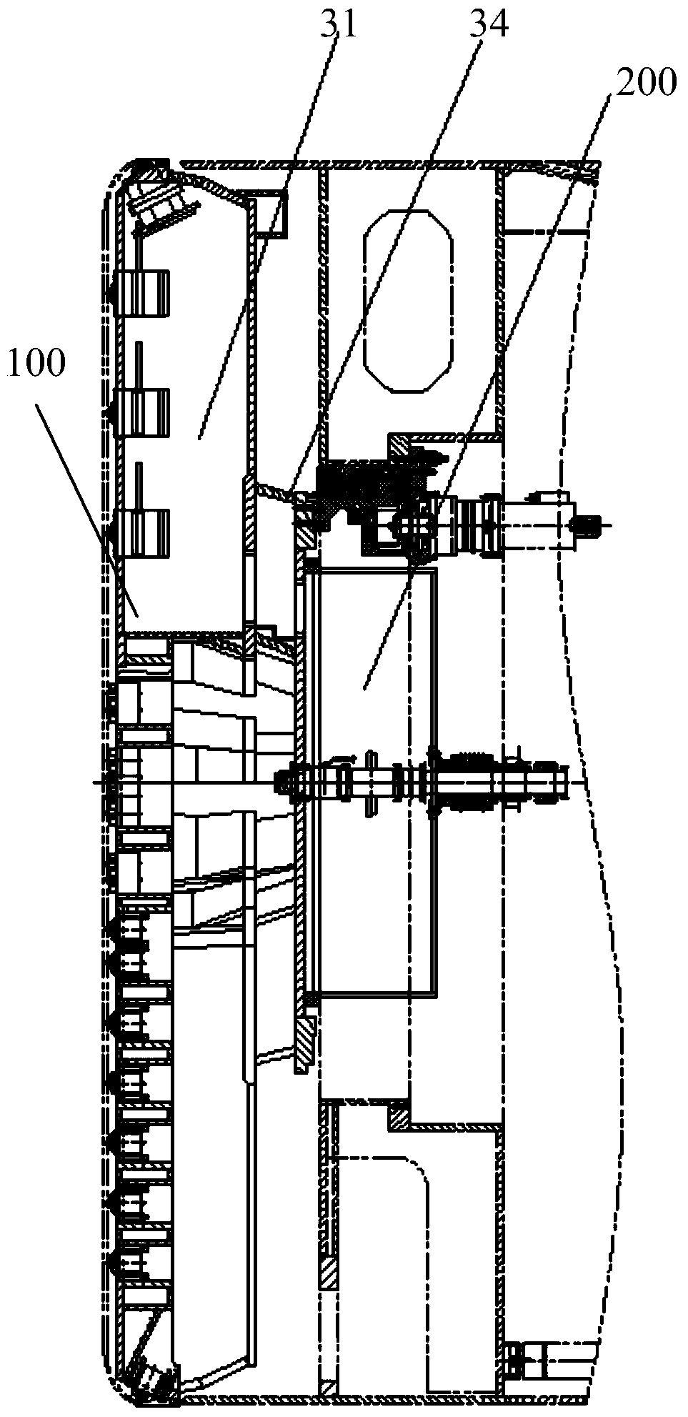
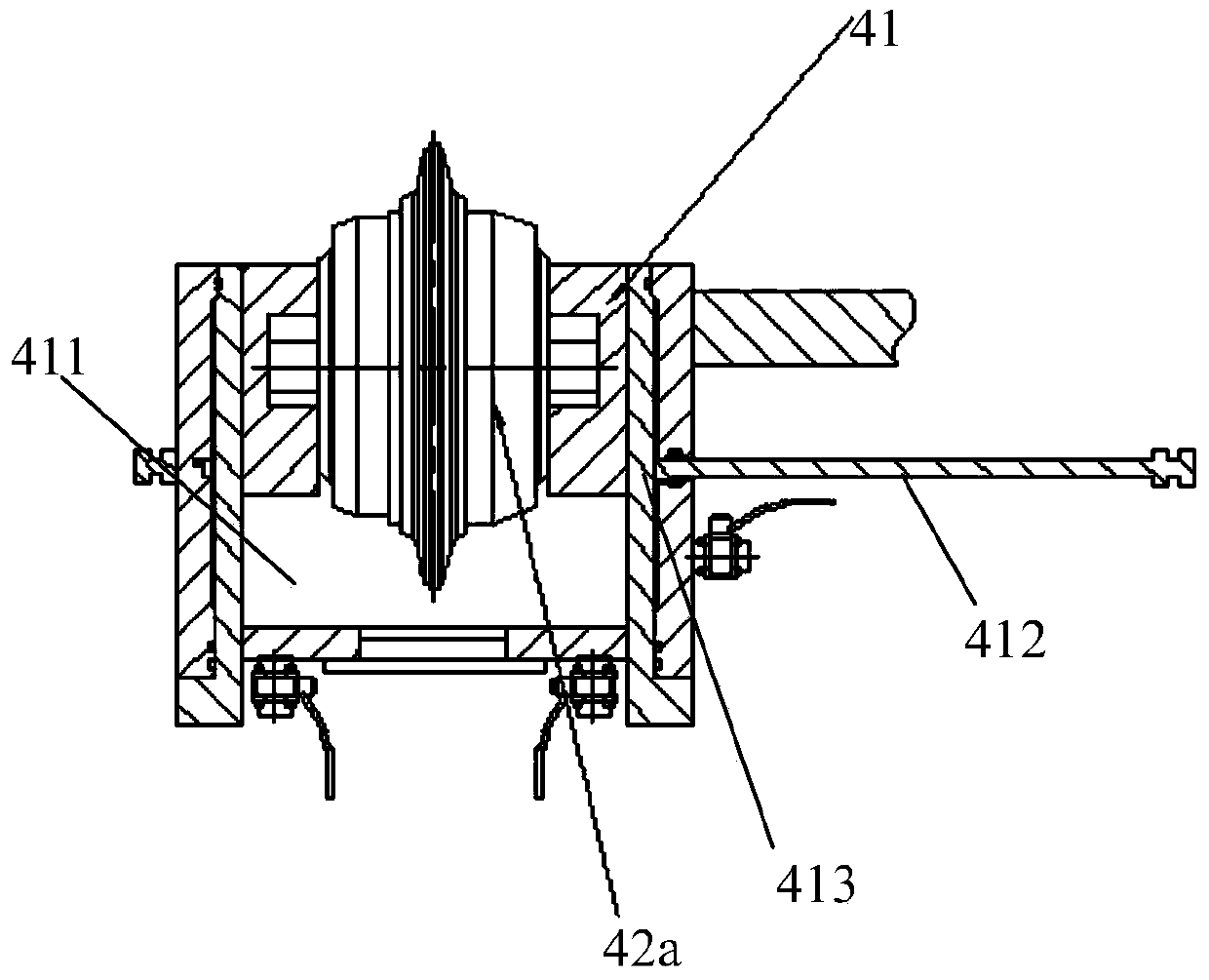
Cutter and shield machine of shield machine

A technology of shield machine and cutter head, applied in the field of shield machine, can solve the problems of improper operation, high cost, long time consumption, etc., and achieve the effect of shortening tool change time, ensuring personal safety, and ensuring smooth progress.

Active Publication Date: 2019-05-24
CHINA RAILWAY CONSTR HEAVY IND
View PDF7 Cites 0 Cited by
  • Summary
  • Abstract
  • Description
  • Claims
  • Application Information

AI Technical Summary

Problems solved by technology

[0002] The cutter head of the existing large-diameter mud-water balance shield machine is mainly equipped with replaceable hobs and cutting tools under pressure. Withstand the high-pressure environment of the mud tank, the tool change process takes a long time, the cost is high, and the improper operation of the step-up and step-down process may cause permanent damage to the health of the operator

Method used


Image

  • Cutter and shield machine of shield machine
  • Cutter and shield machine of shield machine
  • Cutter and shield machine of shield machine

Examples


Embodiment Construction

[0032] Embodiments of the invention are described in detail below, examples of which are illustrated in the accompanying drawings. The embodiments described below by referring to the figures are exemplary and are intended to explain the present invention and should not be construed as limiting the present invention.

[0033] In the description of the present invention, it should be understood that the orientation or positional relationship indicated by the terms "central", "inner", "outer", "radial", "circumferential" etc. is based on the orientation or positional relationship shown in the drawings The positional relationship is only for the convenience of describing the present invention and simplifying the description, but does not indicate or imply that the referred device or element must have a specific orientation, be constructed and operated in a specific orientation, and thus should not be construed as limiting the present invention.

[0034] In the description of the p...


PUM


Abstract

The invention discloses a cutter disc of a shield tunneling machine and the shield tunneling machine. The cutter disc comprises a cutter disc frame which is provided with a front working face, main spoke arms, box type spoke arms and normal-pressure exchanging type cutter components. The box type spoke arms are arranged between every two adjacent main spoke arms and define normal-pressure cavities with inlets and outlets. Each normal-pressure exchanging type cutter component comprises an installation seat, a detachable cutter and a switching part. An installation cavity for installing of a cutter is formed in each installation seat, and the front and back relative position of the cutter and the corresponding switching part can be arranged on the installation seat switchably. Each normal-pressure exchanging type cutter component is arranged on the front surface of the corresponding box type spoke arm. When the cutter disc works, the switching parts are located on the rear sides of the cutters to separate the cutters from the normal-pressure cavities; when the cutters are exchanged, the switching parts are located on the front sides of the cutters, so that the cutters are communicated with the normal-pressure cavities, and the normal-pressure cavities are separated from the surrounding of the front working face of the cutter disc. By means of the cutter disc, operators can exchange the cutters in the normal-pressure environment.

Description

technical field [0001] The invention relates to the technical field of shield machines, in particular to a cutterhead of a shield machine and a shield machine. Background technique [0002] The cutter head of the existing large-diameter mud-water balance shield machine is mainly equipped with replaceable hobs and cutting tools under pressure. Under the high-pressure environment of the mud tank, the tool change process is time-consuming and expensive, and the improper operation of the step-up and step-down process can easily cause permanent damage to the health of the operator. Contents of the invention [0003] The present invention aims to solve one of the technical problems in the related art at least to a certain extent. For this reason, the present invention proposes a cutter head of a shield machine, which can realize the tool change by the operator under normal pressure, which facilitates the tool change and ensures the personal safety of the operator. [0004] The...

Claims


Application Information

Patent Timeline
Patent Type & Authority Patents(China)
IPC IPC(8): E21D9/08
CPCE21D9/08
Inventor 暨智勇薛静任勇
Owner CHINA RAILWAY CONSTR HEAVY IND
Why Eureka
Try Eureka