Method for laying trenchless new pipeline

A laying method and non-excavation technology, applied in tunnels, tunnel linings, mining equipment, etc., can solve problems such as inability to achieve non-excavation or micro-excavation, impact on construction efficiency, and large excavation length, etc., to achieve the laying length Unrestricted, improve construction efficiency and reduce damage

Pending Publication Date: 2021-04-16
天津倚通科技发展有限公司
View PDF7 Cites 0 Cited by
  • Summary
  • Abstract
  • Description
  • Claims
  • Application Information

AI Technical Summary

Problems solved by technology

[0003] However, for the laying of new pipes, it is not yet possible to do trenchless or micro-excavation
Most of the existing pipelines are cement pipelines spliced ​​by cement joints or composite pipelines spliced ​​by spliced ​​segments. Regardless of the form, there are the following problems in the specific construction process: 1. At least Excavating the working well of the equipment and the delivery well connected to the working well for feeding a piece of pipe material, the excavation length is relatively large, and the construction is inconvenient; The hydraulic jack at the place is completed. In order to transport and splice smoothly, it is necessary to provide sufficient support for the back of the hydraulic jack. If the soil is soft, it will bring difficulties to the construction; 3. According to the length of the pipeline to be laid, it needs to match the corresponding If the pipeline is too long, it is necessary to set up a relay station in the middle, which will not only increase the equipment, but also affect the construction efficiency

Method used


Image

  • Method for laying trenchless new pipeline
  • Method for laying trenchless new pipeline

Examples


Embodiment Construction

[0023] Embodiments of the present invention are described in further detail below in conjunction with the accompanying drawings:

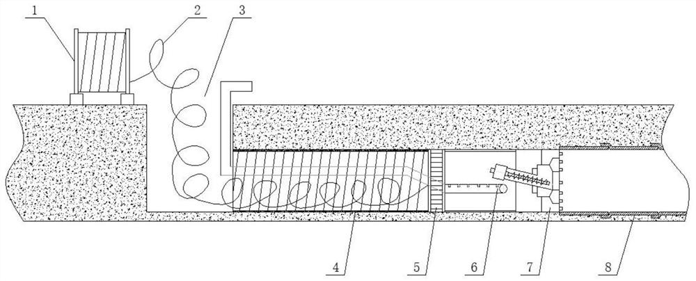
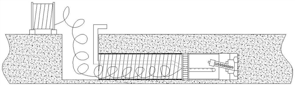
[0024] A method for laying a new pipeline without excavation, the innovation is that it includes the following steps:

[0025] The first step is to excavate a starting pit 3 and a receiving pit at the starting point and the receiving point according to the size of the new pipeline to be laid, or use the inspection shaft of the original pipeline as the starting pit and the receiving pit respectively, and place the shield The machine and the head walking type spiral winding machine 5 are hoisted into the starting pit respectively, and the bracket 1 for winding the profile 2 is set on one side of the starting pit on the ground;

[0026] In the second step, use the cutting head 7 of the shield machine to break and cut the soil or the old pipeline 8, and then use the soil conveying device 6 of the shield machine to transport the broken soil or the old p...


PUM


Abstract

The invention relates to a method for laying a trenchless new pipeline. The method comprises the following steps that 1, a starting pit and a receiving pit are dug in a starting position and a receiving position respectively, and a shield tunneling machine and a machine head walking type spiral winding machine are hoisted into the starting pit; 2, after a cutting machine head of the shield tunneling machine is used for smashing and cutting soil or an old pipeline, a soil conveying device of the shield tunneling machine is used for conveying the smashed soil or the old pipeline to the ground, the cutting machine head of the shield tunneling machine walks forwards, the machine head walking type spiral winding machine is used for forming a plastic profile into a new plastic pipeline, and meanwhile a grouting machine is used for carrying out grouting reinforcement treatment between the outer wall of the new plastic pipeline and the soil; and 3, when the shield tunneling machine reaches the receiving pit, the shield tunneling machine is hoisted, and the laying process of the whole new pipeline is completed. The method is scientific and reasonable in design and has the advantages that construction is convenient, the construction efficiency is improved, the construction cost is saved, the method is not affected by soil quality, the laying length is not limited, and implementation is easy.

Description

technical field [0001] The invention belongs to the field of pipeline laying, and relates to a technique for laying pipelines without excavation, in particular to a method for laying new pipelines without excavation. Background technique [0002] After years of development, the laying technology of the non-excavation repair pipeline is relatively mature. It is a repair method that uses mechanical winding to form a new pipeline lining in the original pipeline with strip profiles. Compared with the traditional technology of excavating and replacing pipes, it has great advantages such as no impact on traffic, reduced environmental pollution, short construction time, fewer construction personnel, high safety, and low overall cost. The introduction of non-excavation repair technology has greatly improved the possibility of upgrading urban underground pipelines. [0003] However, for the laying of new pipes, it is currently not possible to do trenchless or micro-excavation. Most...

Claims


Application Information

Patent Timeline
IPC IPC(8): E21D9/08E21D9/12E21D11/10
Inventor 杨心宇王刚王卓王德智
Owner 天津倚通科技发展有限公司
Why Eureka
Try Eureka