
Device for achieving continuous power supply of instruments in rotating device operation field

A technology for rotating equipment and job sites. It is applied to electromechanical devices, wind turbines, and mechanical equipment in the same direction as the wind. It can solve the problems of production loss, high cost, and complicated wiring. It is easy to operate and save energy. Effect

Active Publication Date: 2016-04-13
SHANGHAI QINSUN ELECTRIC CO LTD
View PDF11 Cites 0 Cited by
  • Summary
  • Abstract
  • Description
  • Claims
  • Application Information

AI Technical Summary

Problems solved by technology

Usually, there are two main ways to realize the power supply of these instruments: one is external power supply; The wiring in the middle is more complicated and the cost is higher; although the power supply method using the battery is relatively safe, the frequent shutdown of the industrial production to replace the battery is also a great loss and potential risk for the production of the enterprise, which is an unsustainable development. Way

Method used


Image

  • Device for achieving continuous power supply of instruments in rotating device operation field
  • Device for achieving continuous power supply of instruments in rotating device operation field
  • Device for achieving continuous power supply of instruments in rotating device operation field

Examples


Embodiment

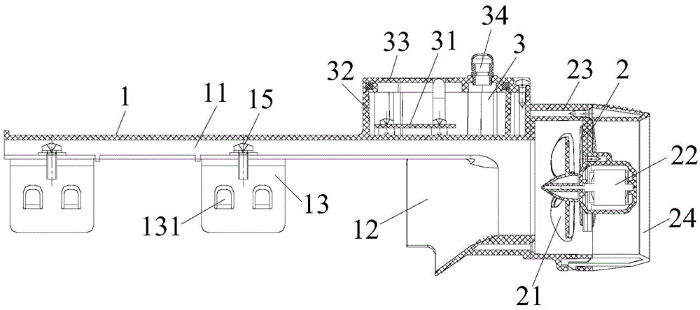
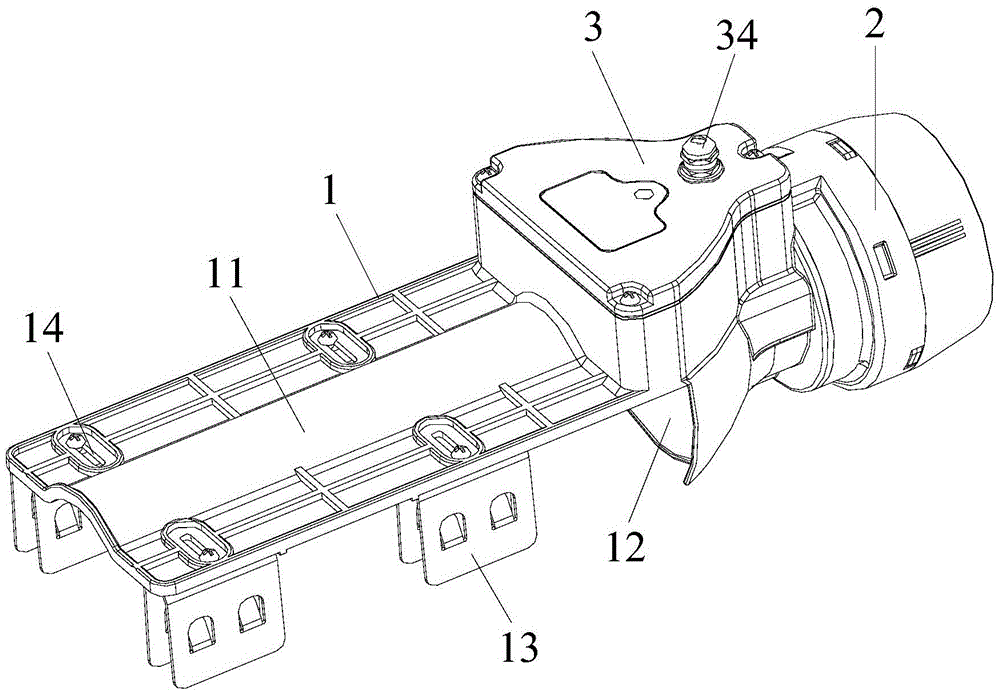
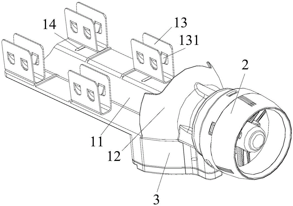
[0025] to combine Figure 1 to Figure 3 As shown: a device provided in this embodiment to realize continuous power supply of instruments and meters at the working site of rotating equipment, including a wind collecting hood 1, a wind power generation unit 2 and an output power supply unit 3, the wind collecting hood 1 is set on the drive rotating equipment On the wind channel of the air-cooled motor (not shown in the figure), the wind power generation unit 2 is arranged at the tail of the wind collecting hood 1, the wind power generation unit 2 is electrically connected to the output power supply unit 3, and the output power supply The unit 3 is respectively electrically connected to the instruments and meters (not shown in the figure) at the rotating equipment operation site.

[0026] In this example:

[0027] The wind collecting hood 1 includes an air guide part 11 and an air intake port 12, the air guide part 11 is arranged on the air flow channel formed by the cooling rib...


PUM


Abstract

The invention discloses a device for achieving continuous power supply of instruments in a rotating device operation field. The device comprises an air collecting hood, a wind power generating unit and an output power supply unit. The air collecting hood is arranged on an air runner of an air cooling motor driving a rotating device. The wind power generating unit is arranged at the tail of the air collecting hood. The wind power generating unit is electrically connected with the output power supply unit. The output power supply unit is electrically connected with the instruments in the rotating device operation field. Cooling air of the air cooling motor driving the rotating device is recycled for power generation, the purpose of continuous power supply of the instruments in the rotating device operation field is achieved, and energy consumption can be obviously reduced. Meanwhile, using and operating are convenient, an effective guarantee is provided for safety production, the device can be widely applied to various places with rotating devices, the requirements for energy saving, environment friendliness and safety production are obviously met, and the practical value is achieved.

Description

technical field [0001] The invention relates to a power supply device, in particular to a device for realizing continuous power supply of instruments and meters at the working site of rotating equipment. Background technique [0002] Rotating equipment is commonly used in industrial enterprises, and as the driving equipment of rotating equipment, the motor is a common equipment that converts electrical energy into mechanical energy. Because the motor will generate a lot of heat during operation, it is necessary to install cooling on the motor. mechanism. The cooling mechanism of the existing motor generally uses air-cooling. The common air-cooled motor is to install the fan on the end of the motor shaft protruding from the rear end cover of the motor. Extended cooling ribs are arranged at intervals, and air flow channels are formed between two adjacent cooling ribs. There is a fan cover outside the fan. When the motor is running, the fan rotates, and the air enters from the...

Claims


Application Information

Patent Timeline
Patent Type & Authority Applications(China)
IPC IPC(8): F03D9/25F03D1/04F03D9/30H02K9/06
CPCF03D1/04F05B2240/911H02K9/06Y02E10/72Y02E10/728Y02P70/50
Inventor 周友山綦联声王旭辉黄秋平
Owner SHANGHAI QINSUN ELECTRIC CO LTD
Learn More