Nonmetal air cylinder for electromagnetic compatibility test and antenna device and system with adjustable rotation angle
A non-metallic cylinder, rotation angle technology, applied in the direction of antenna support/installation device, measuring device, measuring device casing, etc., can solve the problems affecting the electromagnetic compatibility test effect of products, electromagnetic disturbance, antenna test signal interference, etc., to achieve The effect of antenna multi-dimensional space positioning, strong reliability and convenient operation
- Summary
- Abstract
- Description
- Claims
- Application Information
AI Technical Summary
Problems solved by technology
Method used
Image

Examples
Embodiment 1
[0032] Embodiment 1 A kind of non-metallic cylinder for electromagnetic compatibility test
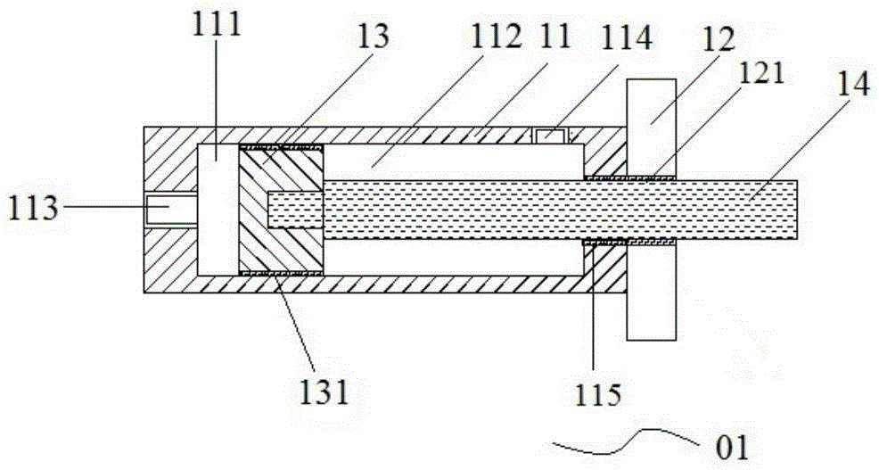
[0033] figure 1 It is a cross-sectional view of the non-metallic cylinder 01 used for the electromagnetic compatibility test provided by the embodiment of the present invention.
[0034] Such as figure 1 As shown, the non-metallic cylinder 01 used in the electromagnetic compatibility test provided in the embodiment of the present invention includes a first cylinder body 11, an end cover 12, accommodated in the first cylinder body 11 and divides the first cylinder body 11 into a second cylinder body. The piston 13 of the first chamber 111 and the second chamber 112, the first through hole 113 that is arranged on the wall of the first cylinder body 11 and communicates with the first chamber 111, is arranged on the wall of the first cylinder body 11 and communicates with the second chamber The chamber 112 communicates with the second through hole 114 and the first piston rod 14, wherein...
Embodiment 2
[0040] Embodiment 2 An antenna device with adjustable rotation angle
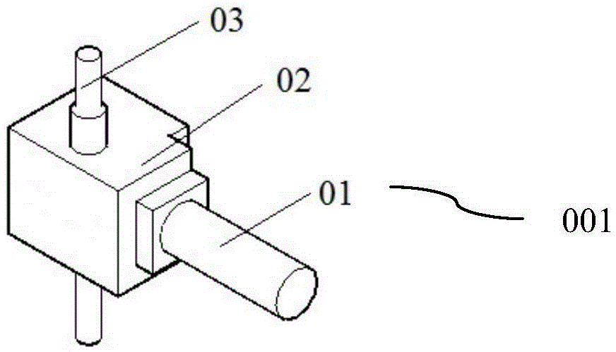
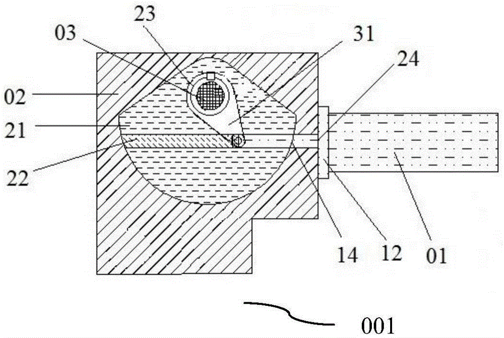
[0041] figure 2 It is a schematic structural diagram of the antenna device 001 with adjustable rotation angle provided in Embodiment 2 of the present invention; image 3 It is a cross-sectional view of the antenna device 001 with adjustable rotation angle provided by the embodiment of the present invention.
[0042] Such as Figure 2-3 As shown, the antenna device 001 with adjustable rotation angle provided in Embodiment 2 of the present invention includes the non-metallic cylinder 01 provided by the present invention for electromagnetic compatibility testing, and also includes a connecting piece 02 and an antenna 03, wherein,
[0043] The connector 02 includes: a hollow cavity 21, a cavity 22 opened in the cavity 21, a first mounting hole 23 disposed in the cavity 21 and penetrating the upper and lower sides of the connector 02, communicating with the cavity 22 The second mounting hole 24;
[0044] Th...
Embodiment 3
[0050] Embodiment 3 An antenna device with adjustable rotation angle
[0051] Figure 4 It is a schematic structural diagram of the antenna device 002 with adjustable rotation angle provided in Embodiment 3 of the present invention; Figure 5 It is a schematic diagram of the connection between the first connector 02 and the second connector 06 provided by the embodiment of the present invention; Figure 6 It is a schematic diagram of horizontal placement of the antenna 03 of the antenna device 002 with adjustable rotation angle provided by the embodiment of the present invention.
[0052] Such as Figure 4 As shown, the antenna device 002 with adjustable rotation angle provided in Embodiment 3 of the present invention adopts the non-metallic cylinder 01 provided by the present invention for electromagnetic compatibility testing, the first connecting member 02, the antenna 03, and also includes the antenna frame 04 , the connecting arm 05 connected to the antenna stand 04, a...
PUM
 Abstract
Description
Claims
Application Information
 - R&D Engineer
- R&D Manager
- IP Professional
- Industry Leading Data Capabilities
- Powerful AI technology
- Patent DNA Extraction
Browse by: Latest US Patents, China's latest patents, Technical Efficacy Thesaurus, Application Domain, Technology Topic.
© 2024 PatSnap. All rights reserved.Legal|Privacy policy|Modern Slavery Act Transparency Statement|Sitemap