Rectangle substrate integrated waveguide back cavity linear polarization antenna

A substrate-integrated waveguide and linear polarization technology, applied in the microwave field, can solve the problems of high processing cost and large volume, and achieve the effects of reduced production cost, high gain, and excellent radiation characteristics

Inactive Publication Date: 2008-05-21
舟山亿佳电子科技有限公司
View PDF0 Cites 12 Cited by
  • Summary
  • Abstract
  • Description
  • Claims
  • Application Information

AI Technical Summary

Problems solved by technology

However, the traditional back cavity is composed of a smooth metal cavity, which is large in size and high in processing costs.

Method used


Image

  • Rectangle substrate integrated waveguide back cavity linear polarization antenna
  • Rectangle substrate integrated waveguide back cavity linear polarization antenna
  • Rectangle substrate integrated waveguide back cavity linear polarization antenna

Examples


Embodiment Construction

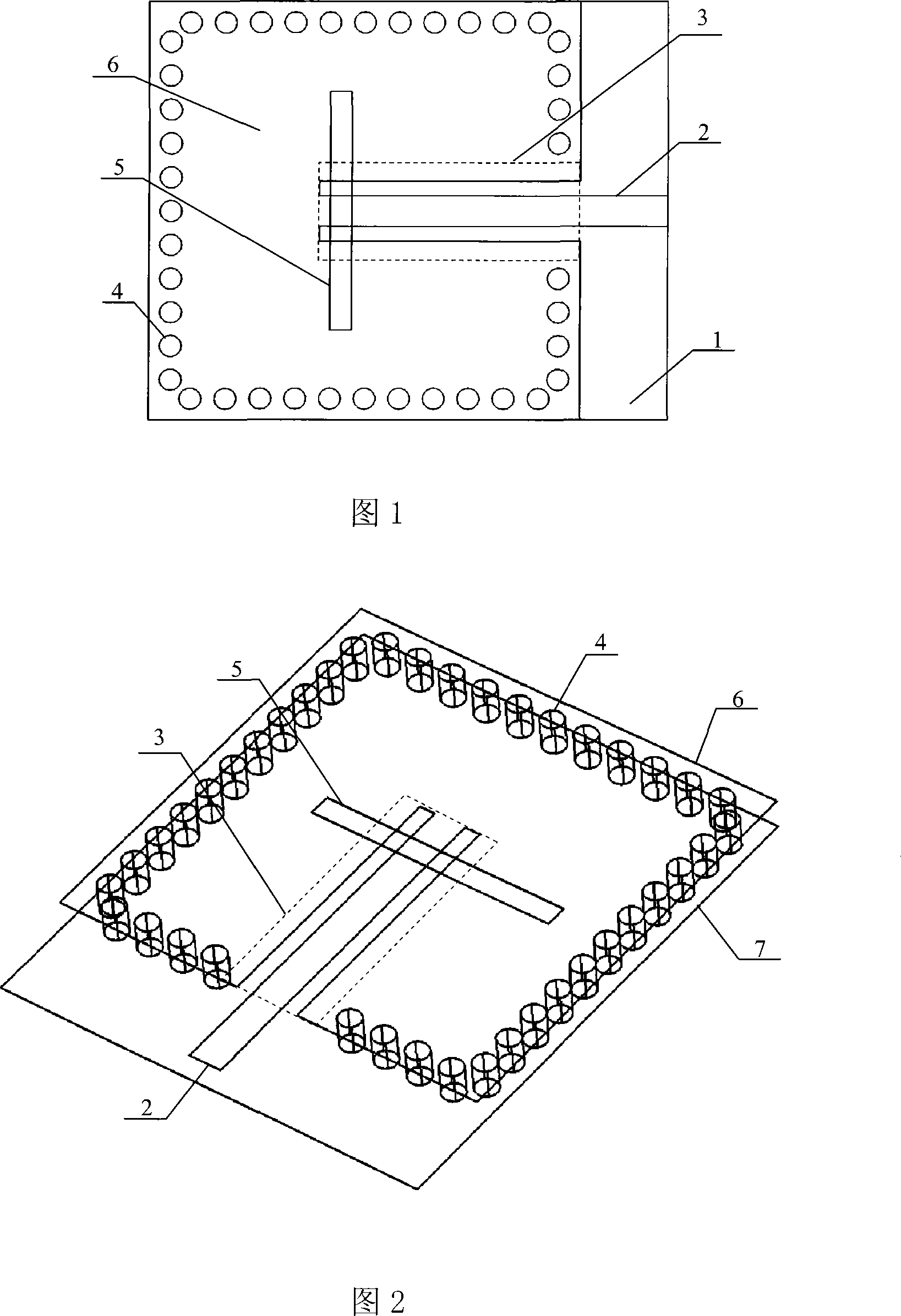
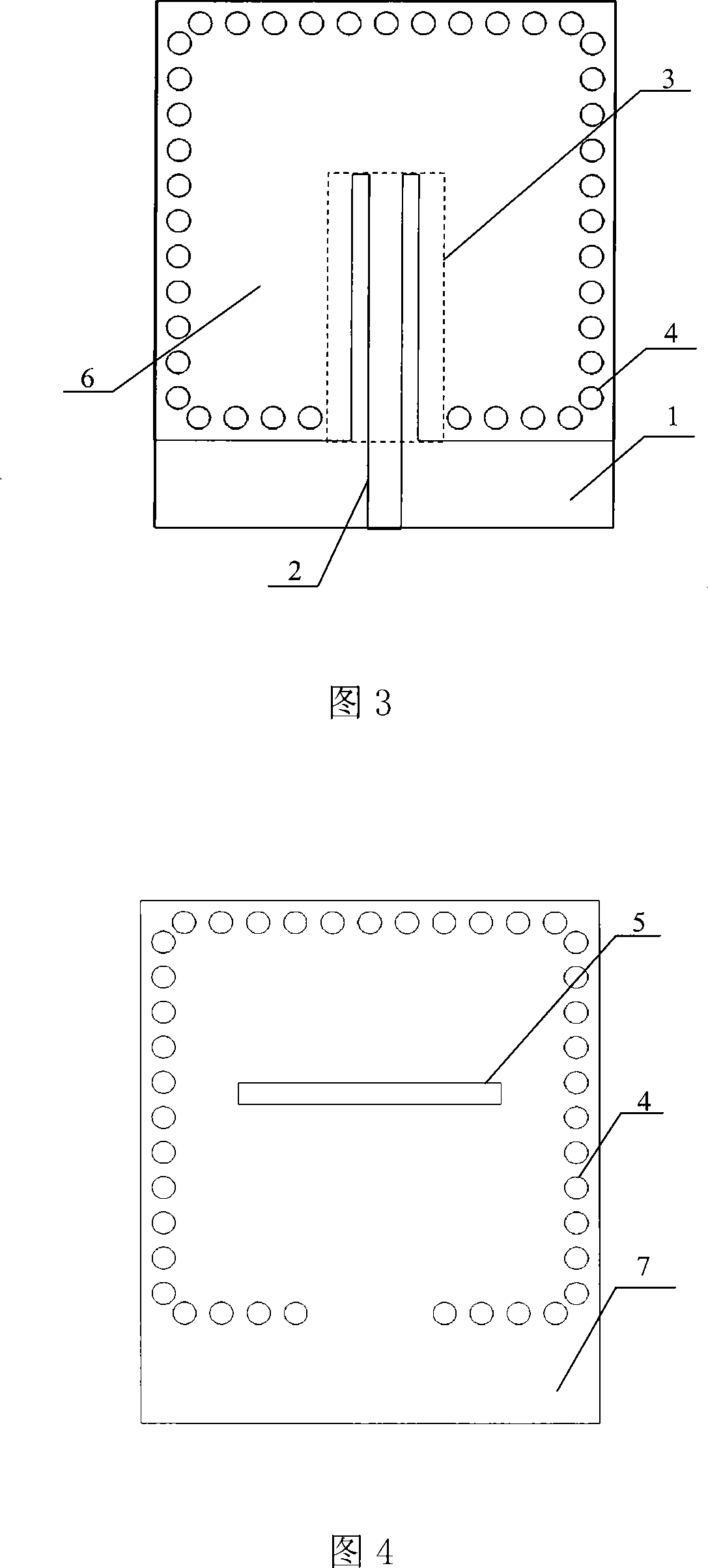
[0022] As shown in Figures 1 and 2, the rectangular substrate integrated waveguide cavity-backed linearly polarized antenna includes a Rogers5880 dielectric substrate 1 with a thickness of 0.5 mm. The two sides of the dielectric substrate 1 are coated with metal layers, which are the upper metal layer 6 and the lower metal layer respectively. Layer 7, wherein the lower metal layer 7 serves as the formation. As shown in Figure 3, the upper metal layer 6 is etched with a microstrip line 2 for feeding and a coplanar waveguide transmission line 3 (included in the dotted line frame). The coplanar waveguide transmission line 3 is a common ground coplanar waveguide structure, and its middle metal strip The external extension is used as the microstrip line 2. The length and width of the microstrip line 2 are 4 mm and 1.45 mm respectively, and the two air gaps of the coplanar waveguide transmission line 3 both have a width of 0.7 mm and a length of 12 mm. A through hole with a diamete...


PUM


Abstract

The invention relates to a polarized antenna with wave guiding cavity-backed lines integrated on a rectangular substrate. The traditional polarized antenna has the disadvantages of low performance of single radiation unit, large bulk, complex structure and high manufacturing cost. The dielectric substrate of the invention is plated with metallic layers on two sides; the upper metallic layer is etched with a microstrip line for feeding and a plurality of coplanar wave guiding transmission lines; the coplanar wave guiding transmission lines are grounded coplanar wave guiding structure, wherein, the metallic strip in the middle is extended outwards to form the microstrip line. A plurality of metallized through holes, which are arrayed as a square, are penetrated through the upper metallic layer, the medium substrate and the lower metallic layer to form the cavity; the coplanar wave guiding transmission lines are extended into the cavity. An elongated radiation slit is etched on the lower metallic layer corresponding to the cavity. The invention has the advantages that: by adopting the general PCB technology, the production cost is notablely decreased and the invention can be integrated with the microstrip circuit without seam, the integrity of the system is improved; compared with the exact machining of the traditional cavity-backed antennas, the manufacture speed is high and the cost is low.

Description

technical field [0001] The invention belongs to the field of microwave technology, and relates to a rectangular substrate-integrated waveguide cavity-backed linearly polarized antenna based on substrate-integrated waveguide technology. Communication systems are especially suitable for applications where the received signal is weak and a high-gain antenna is required. Background technique [0002] As a key component of a communication system, antennas are widely used in wireless communication occasions. The performance of the antenna directly determines the performance of the entire system. A high-performance antenna can not only significantly improve the performance of the system and obtain a good reception effect, but also greatly relieve the index pressure of the subsequent RF circuit and reduce the cost of the system. Especially in space applications such as radars and satellites, the demand for antennas is not only excellent radiation performance, but also has strict r...

Claims


Application Information

Patent Timeline
Patent Type & Authority Applications(China)
IPC IPC(8): H01Q1/38H01Q13/10H01Q13/06
Inventor 罗国清孙玲玲
Owner 舟山亿佳电子科技有限公司
Why Eureka
Try Eureka