Fastener

A technology for fasteners and threads, which is applied in the field of fasteners with tensile strength and anti-loosening, and can solve the problems that the threads cannot bear the screw-in torque, damage the lock, and the cutting ability of the notch 141 is not good enough, etc.

Inactive Publication Date: 2016-04-13
TAIWAN SHAN YIN INT CO LTD
View PDF8 Cites 0 Cited by
  • Summary
  • Abstract
  • Description
  • Claims
  • Application Information

AI Technical Summary

Problems solved by technology

[0005] In view of the cutting ability of these screw teeth 14, different effects are produced by the setting angles of these slit angles 146, that is, when the angles of these slit angles 146 are set too small, the cutting process of these screw teeth 14 In the action of fast locking and entering the locking object, the fibers of the locking object cannot effectively enter these incisions 141 due to the characteristic of elastic recovery force, so that these incisions 141 cannot effectively assist the screw teeth 14 The function of turning the locking object makes the cutting function provided by the slit 141 limited, or even ineffective, and it is even more impossible to guide the screw 1 to penetrate into the locking object; on the contrary, if these slit angles 146 are set too If the size of these threads 14 is large, the size of these threads 14 may be relatively reduced. On the contrary, the turning ability of the notch 141 is not as good as the smaller turning ability of the notch 141 due to the excessive factor of the notch angle 146. At the same time, this size is relatively large. Due to its thin structure, the small thread 14 cannot effectively bear the locking torque, and is prone to tooth collapse, which needs to be improved.
[0006] 2. Cannot reduce locking torque:
[0007] Since the thread 14 is formed smoothly in order to effectively form it, a tooth plate (not shown in the figure) is used for rapid rolling and forming on the rod body 11. Therefore, when the thread 14 is synchronously formed on the rod body 11, That is to say, uneven shapes will be formed on the rod body 11 synchronously, and because these uneven shapes are formed on the rod body 11, it will cause the screw 1 to have poor bending and torque during the locking process, and then The fastening force of the lock is reduced, and during the locking process, these uneven parts on the rod body 11 cannot sustain the locking stress and are excessively twisted, or even broken; The effect is limited by the angle 144 of the design angle 144 of the angle between the crests of these threads 11, and there are different effects. cutting ability, but when encountering a hard locking object, it is very easy to cause the screw teeth to be unable to withstand a large screw-in torque, and there are damages and lack of locking. On the contrary, these screw teeth 14 When the tooth peak angle 144 is larger, although the thread 14 can withstand the torsion better, the cutting effect is not as good as that of the thread 14 with a smaller tooth peak angle 144, and there will still be problems such as incomplete locking. Generated, so the use is limited and needs to be improved

Method used


Image

  • Fastener
  • Fastener
  • Fastener

Examples


Embodiment Construction

[0054] In order to further explain the technical solution of the present invention, the present invention will be described in detail below through specific examples.

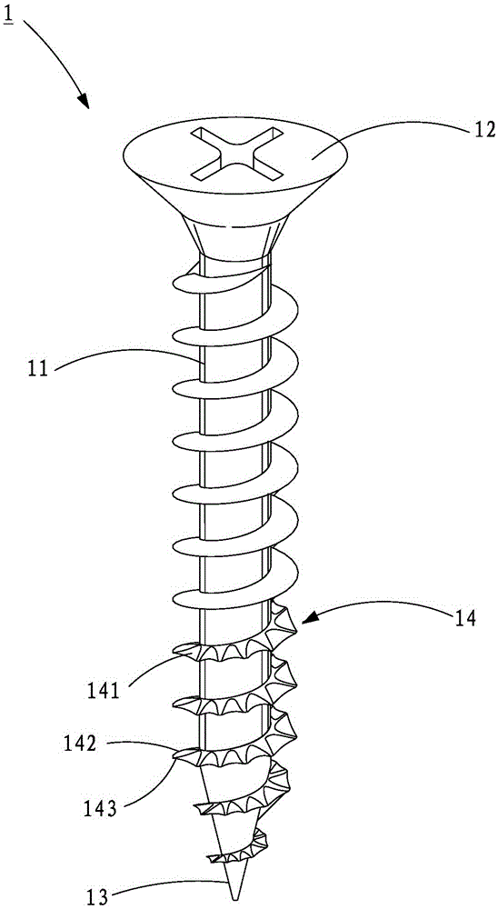
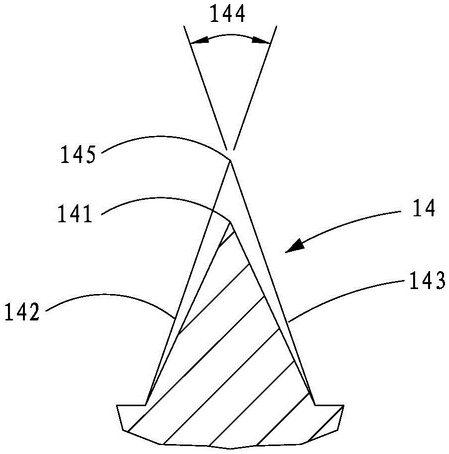
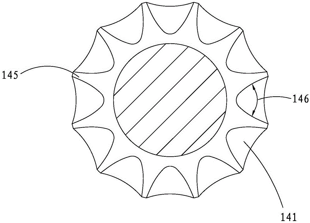
[0055] refer to Figure 4 to Figure 6, the first preferred embodiment of the fastener 3 of the present invention, which includes a rod body 31, a screw head 32 provided on the rod body 31, a lock opposite to the screw head 32 and provided at the other end of the rod body 31 part 33, and a plurality of first threaded teeth 34 and second threaded teeth 35 respectively arranged on the rod body 31; wherein, each first threaded thread 34 extends from the locking part 33 to the direction of the screw head 32 and is arranged around the ring. On the rod body 31, each first thread 34 has a first upper tooth surface 341 extending downward from the rod body 31, a first lower tooth surface 342 extending upward from the rod body 31, and a The first crest 343 formed by the connection of the first upper and lower tooth surfa...


PUM


Abstract

The invention discloses a fastener. Mainly, a plurality of first threads and a plurality of second threads are arranged on a rod body. Meanwhile, an outward-protruding backstop rib is arranged at the position, among any two first threads and any two second threads annularly arranged on the corresponding first threads, of the periphery of the rod body. The backstop ribs extend from the periphery of the rod body and are connected to first upper thread faces of the first threads and second upper thread faces of the second threads annularly arranged on the first threads. Meanwhile, the inclination angle of the backstop ribs and the periphery of the rod body are arranged in a conical shape with 5-10 degrees. Thus, grooves in the second threads are used for assisting in cutting objects and containing cuttings, the first threads are used for reinforcing the drilling and locking stress of the second threads, and then the backstop ribs are used in a matched manner in good time to increase the torsion resisting force and tensile resisting force in the drilling and locking process, so that the function of preventing loosening and retreating after drilling and locking is achieved, and the locking fastening force and the locating effect are greatly improved.

Description

technical field [0001] The invention relates to a fastener, in particular to a fastener with tensile force and anti-loosening. Background technique [0002] refer to Figure 1 to Figure 3 , U.S. Publication No. 20050186048 Patent Application Screw 1 includes a rod body 11, a screw head 12 arranged on the rod body 11, a locking portion 13 opposite the screw head 12 and located at the other end of the rod body 11, and many A thread 14 ring is set on the rod body 11; wherein, the thread 14 is provided with a plurality of connected cutouts 141, and each thread 14 has an upper tooth surface extending downward from the rod body 11 142, a lower tooth surface 143 extending upward from the rod body 11, and a tooth crest angle 144 formed by the intersection of the upper and lower tooth surfaces 142, 143, and the apex formed by the tooth crest angle 144 intersects to form Vertex 145, each slit 141 forms a setting with a slit angle 146; therefore, when the screw 1 performs locking oper...

Claims


Application Information

Patent Timeline
Patent Type & Authority Applications(China)
IPC IPC(8): F16B39/282F16B25/02F16B25/10
Inventor 苏国材苏昱荣
Owner TAIWAN SHAN YIN INT CO LTD
Why Eureka
Try Eureka