

Rotating shaft of automobile generator
A technology for automotive generators and rotating shafts, applied in shafts, shafts, bearings, mechanical equipment, etc., can solve the problems of poor positioning of rotating shafts, low efficiency of press-fitting work, and easy deformation of shaft heads, and improve installation efficiency and quality , Reduce the probability of deformation and reduce the effect of stress
Inactive Publication Date: 2016-04-13
CHANGZHOU BEIANTE POWER MACHINERY
View PDF5 Cites 1 Cited by
- Summary
- Abstract
- Description
- Claims
- Application Information
AI Technical Summary
Problems solved by technology
Due to the relatively high pressure during press-fitting, the shaft head generally cannot bear force, and there is no end face that can be positioned on the traditional shaft, so it is difficult to position the shaft during press-fitting, and the shaft head is easily deformed when the force is too large, and the press-fitting work efficiency Low
Method used
View moreImage
Smart ImageViewing Examples

Examples
specific Embodiment approach
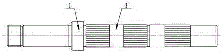
[0012] Examples, see attached figure 1 , a rotating shaft of an automobile generator, comprising a step 1 and a body 2, the left end of the body 2 is processed with an external thread, the body 2 is provided with a step 1, the body 2 is provided with a spline groove and is located on the right side of the step 1 On the side, there are three spline grooves, and the optical axis is between adjacent spline grooves.
[0013] Preferably, chamfers are provided on the left and right end surfaces of the body 2 .
[0014] Preferably, an undercut groove is provided on the right side of the thread at the left end of the body 2 .
Login to View More PUM
 Abstract
The invention discloses a rotating shaft of an automatic generator. The rotating shaft comprises a step and a body. The left end of the body is provided with an external thread. The body is provided with the step. The body is provided with three spline grooves located at the right side of the step. The parts, between the spline grooves, of the rotating shaft are polished shaft bodies. By adopting the rotating shaft of the automatic generator, the problems that a rotating shaft is hard to position in the press-fitting process and the head of the shaft deforms easily due to excessive stress in the prior art are solved.
Description
technical field [0001] The invention relates to the technical field of power generation, in particular to a rotating shaft of an automobile generator. Background technique [0002] The generator shaft is made of 40Cr material. In the rotor, it wears the claw pole, the inner retaining ring and the slip ring together. It has a very important position, so the requirements for it are relatively high. Due to the relatively high pressure during press-fitting, the shaft head generally cannot bear force, and there is no end face that can be positioned on the traditional shaft, so it is difficult to position the shaft during press-fitting, and the shaft head is easily deformed when the force is too large, and the press-fitting work efficiency Low. Contents of the invention [0003] According to the above deficiencies, the present invention provides a rotary shaft of an automobile generator. [0004] In order to achieve the above object, the rotating shaft of the automobile genera...
Claims
Login to View More Application Information
Patent Timeline
 Patent Type & AuthorityApplications(China)
IPC IPC(8): F16C3/02
Inventor徐天同
OwnerCHANGZHOU BEIANTE POWER MACHINERY