
Assembling type optical cable cross-connecting cabinet

An optical cable junction box and an assembled technology, which is applied in the field of assembled optical cable junction boxes, can solve the problems such as the relatively large limitation of the optical fiber junction box, the inability to flexibly adjust the capacity of the optical fiber junction box, and the difficulty in the work of the optical fiber line, etc., so as to achieve good capacity expansion, Improve the flexibility and adaptability of use, the effect of flexible and convenient use

Inactive Publication Date: 2016-04-13
HEBEI ZHIFANG COMM EQUIP
View PDF5 Cites 0 Cited by
  • Summary
  • Abstract
  • Description
  • Claims
  • Application Information

AI Technical Summary

Problems solved by technology

[0002] At present, with the rapid development of optical fiber communication networks, the coverage of optical fiber communication lines is getting wider and wider, resulting in a huge amount of transfer box equipment used for optical fiber connection and positioning and a very wide distribution range. In use, it is found that The current optical fiber splice box structure is often a traditional integral structure. Although it can meet the needs of optical fiber connection and positioning, due to its large structural volume and good stability, the current optical fiber splice box is difficult to transport, install and install. Daily fiber optic line maintenance and other aspects of work are difficult. At the same time, with the development of fiber optic networks, the current fiber optic transfer box cannot flexibly adjust its own capacity, resulting in relatively large restrictions in the use of the current fiber optic transfer box. Effectively meet the needs of the development of optical fiber networks, so in view of this phenomenon, it is urgent to develop an inventive optical fiber transfer box to meet the needs of actual production and use

Method used


Image

  • Assembling type optical cable cross-connecting cabinet

Examples


Embodiment Construction

[0013] In order to make the technical means, creative features, achievement goals and effects realized by the present invention easy to understand, the present invention will be further described below with reference to the specific embodiments.

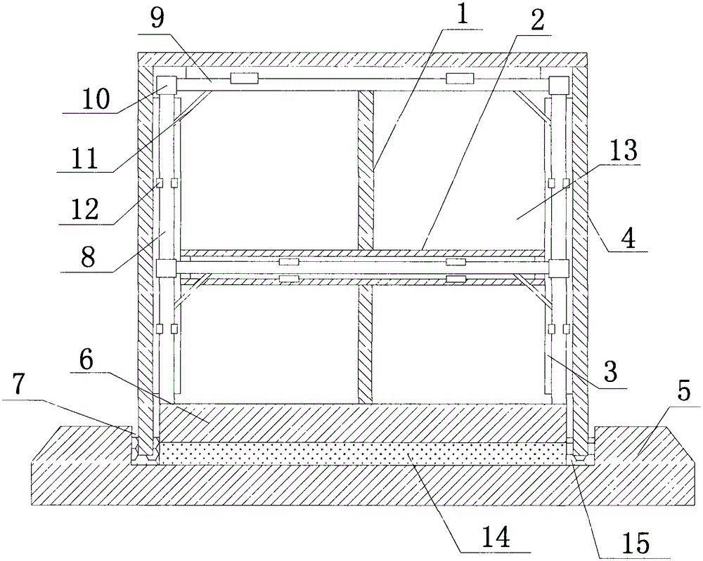
[0014] like figure 1 The described assembled optical cable connection box includes a positioning base, a bearing frame, a bearing plate 1, a partition 2, a guide rail 3 and a protective plate 4, and the positioning base includes a base 5 and a bearing seat 6, wherein the bearing seat 6 is embedded. A positioning groove 7 with a width of 1-5 mm is left on the upper surface of the base 5 and between the base 5. The bearing frame includes a column 8, a beam 9, a shaft sleeve 10 and a reinforcing rib 11, of which at least four columns 8 surround the bearing. The axis of the seat 6 is vertically installed on the upper surface of the bearing seat 6, a number of beams 9 are slidably connected with the column 8 through the shaft sleeve 10, a...


PUM


Abstract

The invention relates to an assembling type optical cable cross-connecting cabinet. The assembling type optical cable cross-connecting cabinet comprises a positioning base, a bearing frame, a bearing plate, a separating plate, guide rails, and protection plates, the positioning base comprises a base and a bearing seat, the bearing frame comprises columns, cross beams, shaft sleeves, and reinforcing ribs, the guide rails are respectively arranged on the columns and the cross beams of the bearing rack via ratchet mechanisms, the numbers of the bearing plate and the separating plate are both at least one, the bearing plate and the separating plate are arranged in the bearing frame via the guide rails, the bearing plate is positioned in a positioning chamber, a plurality of protection plates are arranged on the external surface of the bearing frame in a sliding manner via the guide rails, the adjacent protection plates are mutually connected and form a sealed cavity structure, and end surfaces of the protection plates abutted against the positioning base are all embedded in positioning grooves. According to the assembling type optical cable cross-connecting cabinet, on one hand, dismounting and assembling can be flexibly realized according to the usage requirement; one the other hand, the optical fiber cross-connecting cabinet has good expansion capability, the effective capacity of the optical fiber cross-connecting cabinet can be flexibly adjusted, and the usage flexibility and adaptability of the optical fiber cross-connecting cabinet are improved.

Description

technical field [0001] The invention relates to an optical cable connecting box, specifically an assembled optical cable connecting box. Background technique [0002] At present, with the rapid development of optical fiber communication networks, the coverage area of ​​optical fiber communication lines is getting wider and wider, resulting in a huge use of junction box equipment for optical fiber connection and positioning and an extremely wide distribution range. The structure of the current optical fiber junction box is often a traditional integral structure. Although it can meet the needs of optical fiber connection and positioning, due to its large structure and good stability, the current optical fiber junction box is difficult to transport, install and It is difficult to maintain daily optical fiber lines. At the same time, with the development of optical fiber networks, the current optical fiber junction box cannot flexibly adjust its own capacity. Effectively meet t...

Claims


Application Information

Patent Timeline
Patent Type & Authority Applications(China)
IPC IPC(8): G02B6/44
CPCG02B6/4441G02B6/4444G02B6/4445G02B6/445
Inventor 郭国亮陈学志
Owner HEBEI ZHIFANG COMM EQUIP
Learn More