Sealed isolation connector

A technology of sealing isolation and sealing ring, applied in the direction of cable joints, etc., can solve the problems of complex manufacturing process, long production cycle, inability to use, etc., and achieve the effect of strong adaptability to the environment, long service life and simple structure

Inactive Publication Date: 2016-04-13
成都海鑫立机电科技有限公司
View PDF9 Cites 6 Cited by
  • Summary
  • Abstract
  • Description
  • Claims
  • Application Information

AI Technical Summary

Problems solved by technology

[0002] The current production and application of sealed isolation joints adopt the connector type, which is mainly divided into sockets and pins. The manufacturing process is complicated, and the price is expensive, the production cycle is long, and it cannot be used in special environments.

Method used


Image

  • Sealed isolation connector
  • Sealed isolation connector
  • Sealed isolation connector

Examples


Embodiment Construction

[0010] Embodiments of the present invention will now be described in detail in conjunction with the accompanying drawings.

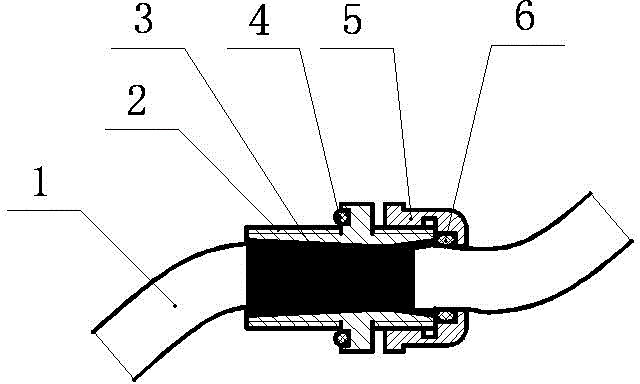
[0011] Such as figure 1 Shown: Sealed isolation joint, including cable (1), base (2), potting compound (3), O-ring seal (4), nut (5), seal ring (6).

[0012] It is characterized in that: the cable (1) is installed in the base (2), the potting glue (3) is installed in the base (2); a groove is opened on the left side of the base (2); the O-shaped sealing ring ( 4) Installed in the groove opened on the left side of the base (2); there is a stepped hole inside the nut (5); the sealing ring (6) is installed in the stepped hole of the nut (5), and set on the cable ( 1) on; the nut (5) and the base (2) are connected by threads.

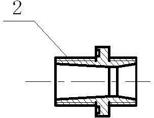
[0013] As shown in Figure 2, taper holes are provided at both ends of the inner cavity of the base (2).

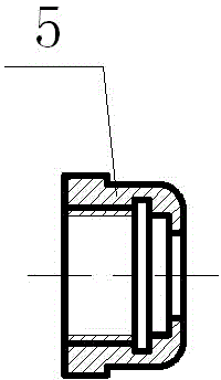
[0014] As shown in Figure 3, a stepped hole is opened on the right side of the inner cavity of the nut (5).

[0015] Such as...


PUM


Abstract

The invention discloses a sealed isolation connector, and the connector comprises a cable (1), a substrate (2), casting glue (3), an O-shaped sealing ring (4), a nut (5), and a sealing ring (6). The connector is characterized in that the cable (1) is disposed in the substrate (2); the casting glue (3) are disposed in the substrate (2); the left side of the substrate (2) is provided with a groove; the O-shaped sealing ring (4) is disposed in the groove disposed at the left side of the substrate (2); the interior of the nut (5) is provided with a stepped hole; the sealing ring (6) is disposed in the stepped hole of the nut (5), and sleeves the cable (1); and the nut (5) is in threaded connection with the substrate (2), and compresses the sealing ring (6). The connector employs a multi-sealing isolation structure, effectively seals and isolates the mixed entering of different mediums, is simple in structure, is convenient to maintain, is long in service life, is good in environment adaptability, and is reliable in waterproof and sealing isolation performances.

Description

technical field [0001] The invention relates to the field of sealing and isolating joints, in particular to a sealing and isolating joint. Background technique [0002] The current production and application of sealed isolation joints adopt the connector type, which is mainly divided into sockets and pins. The manufacturing process is complicated, and the price is expensive, the production cycle is long, and it cannot be used in special environments. Contents of the invention [0003] The purpose of the present invention is to solve the disadvantages of the above-mentioned prior art and provide a utility model of a sealed and isolated joint with simple structure, convenient installation and maintenance, and good sealing and isolation performance. [0004] Such as figure 1 Shown: Sealed isolation joint, including cable (1), base (2), potting compound (3), O-ring seal (4), nut (5), seal ring (6). [0005] It is characterized in that: the cable (1) is installed in the base ...

Claims


Application Information

Patent Timeline
Patent Type & Authority Applications(China)
IPC IPC(8): H02G15/08
Inventor 陈海洁王立云
Owner 成都海鑫立机电科技有限公司
Why Eureka
Try Eureka