Selection method and apparatus for switching node, and base node and terminal nodes

A terminal node and switching node technology, applied in the field of communication, can solve the problems of improper selection of switching nodes, unsmooth information transmission, waste of network traffic, etc., to achieve stable and reliable data communication, reduce burden, and save network traffic.

Active Publication Date: 2016-04-13
TIANJIN WEISHENGWEI TECH CO LTD
View PDF5 Cites 4 Cited by
  • Summary
  • Abstract
  • Description
  • Claims
  • Application Information

AI Technical Summary

Problems solved by technology

[0005] The purpose of the present invention is to provide a method and device for selecting a switching node, a base node, and a terminal node to solve problems in the prior art such as unsmooth information transmission, network congestion, and waste of network traffic due to improper selection of switching nodes

Method used


Image

  • Selection method and apparatus for switching node, and base node and terminal nodes
  • Selection method and apparatus for switching node, and base node and terminal nodes
  • Selection method and apparatus for switching node, and base node and terminal nodes

Examples


Embodiment 1

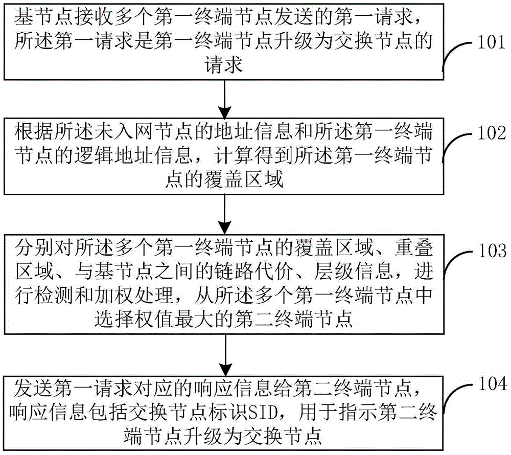
[0045] figure 2 It is a flowchart of a method for selecting a switching node provided in the embodiment of the present application. The execution subject of this embodiment can be the base node, see figure 2 , the selection method of the switching node specifically includes the following steps:

[0046] Step 101, the base node receives first requests sent by multiple first terminal nodes, where the first requests are requests for the first terminal nodes to be upgraded to switching nodes.

[0047] Specifically, the base node may be the aforementioned concentrator; the first terminal node may be the aforementioned electric meter.

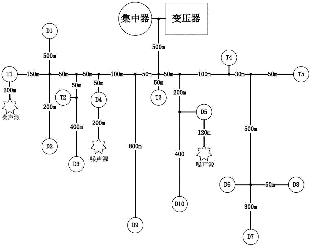
[0048] The first request is triggered according to the first terminal node receiving a data packet sent by a node not in the network, and the first request includes at least a link cost between the first terminal node and the base node and address information of the node not in the network.

[0049] Step 101 In a specific embodiment, for example...

Embodiment 2

[0100] In the foregoing embodiment 1, the method for selecting a switch node is mainly introduced from the perspective of a base node, and in embodiment 2 corresponding to the first embodiment, the method for selecting a switch node is mainly introduced from the perspective of a terminal node. see Figure 7 The flow chart of the switching node selection method provided by the embodiment of the present application is shown. The execution subject of this embodiment may be a terminal node, and the method may include the following steps:

[0101] Step 701. Receive a data packet sent by a non-networked node, the data packet is triggered when the non-networked node does not receive beacon information within a time threshold;

[0102] Specifically, within the time threshold, when the non-network node does not receive the beacon information, the first terminal node receives the data packet sent by the non-network node.

[0103] Step 702: Send a first request to the base node accordi...

Embodiment 3

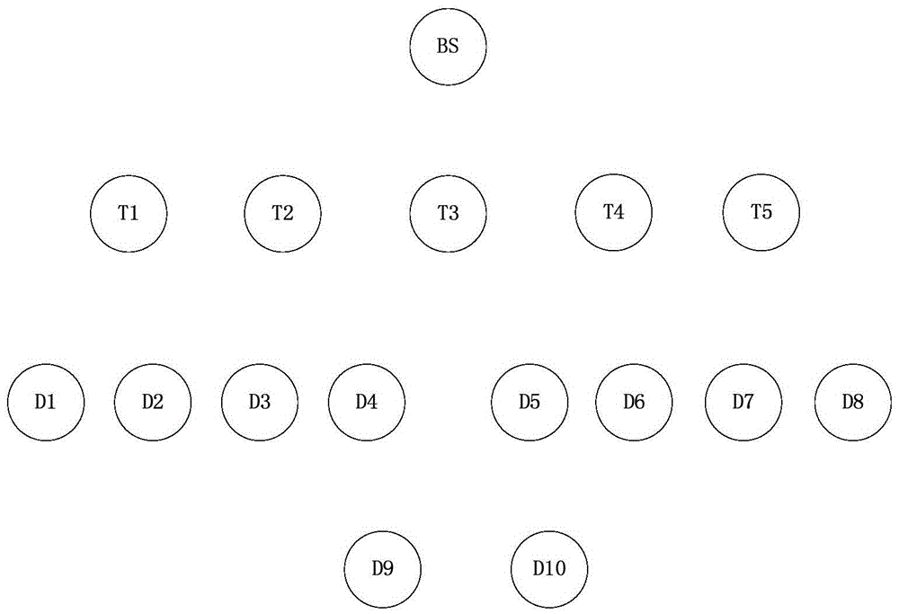
[0110] Corresponding to the switching node selection method provided in the first embodiment of the present application, the embodiment of the present application also provides a base node, and the execution subject may be the base node, for example, a concentrator, see Figure 8 As shown in the schematic diagram of the base node, the base node may specifically include: PLC interface 801, processor 802, memory 803 and network interface 804; system bus 805 is used to connect PLC interface 801, processor 802, memory 803 and network interface 804.

[0111] Memory 803 stores program codes;

[0112] The network interface 804 is used for the concentrator to communicate with the grid background system;

[0113] The processor 802 is used to perform the following operations:

[0114] The first request sent by multiple first terminal nodes is received through the PLC interface 801, the first request is a request for the first terminal node to be upgraded to a switching node, and the fi...


PUM


Abstract

The invention discloses a selection method and apparatus for a switching node, and a base node and terminal nodes. According to the selection method, the coverage regions and the overlapping regions of the multiple terminal nodes, and link costs and hierarchy information between the terminal nodes and the base node are detected and weighted; and a second terminal node with the maximum weight is chosen from the multiple terminal nodes to be upgraded into the switching node. Therefore, the switching node can be used for forwarding information conveniently to enable the base node and the terminal nodes or the nodes without network access to establish connection; consequently, unsmooth communication caused by interference can be avoided when base node transmits message to the long-distanced terminal nodes or the nodes without network access, the communication quality is improved, the load of the base node is lowered, and the network flow is saved; and stable and reliable data communication between an electric meter far from a concentrator and the concentrator can be realized.

Description

technical field [0001] The present invention relates to the field of communication technology, in particular to a method and device for selecting a switching node, a base node, and a terminal node. Background technique [0002] Power line carrier communication PLC (Powerline Communications, referred to as PLC) is a communication method that uses low-voltage power distribution lines to transmit high-speed data, voice, image and other multimedia service signals. Different types of power line carrier communication use different frequency bands. By applying modulation carrier signal to control different frequency bands. After the power is raised to a voltage of hundreds of thousands of volts in the transformer, it reaches the transformer at the power consumption end, and then is decompressed in the transformer at the power consumption end before being delivered to consumers. For example, the transformer divides the power into 70kv, 20kv, 220v, etc., 70kv power is distributed to...

Claims


Application Information

Patent Timeline
Patent Type & Authority Applications(China)
IPC IPC(8): H04L12/721H04B3/54
CPCH04B3/542H04L45/124
Inventor 刘洋
Owner TIANJIN WEISHENGWEI TECH CO LTD
Why Eureka
Try Eureka