Improved control grip

A technology for controlling handles and areas, used in bicycle control systems, bicycle accessories, transportation and packaging, etc., can solve problems such as failure, cable breakage, discomfort, etc., to reduce wear and cost, improve reliability, and improve safety. Effect

Active Publication Date: 2016-04-13
BAYERISCHE MOTOREN WERKE AG
View PDF4 Cites 1 Cited by
  • Summary
  • Abstract
  • Description
  • Claims
  • Application Information

AI Technical Summary

Problems solved by technology

Also, the cable of the handle heating unit of the throttle handle will snap and fail through many movements
[0008] According to the desired acceleration, the position of the throttle handle is unfavorable and uncomfortable from an ergonomic point of view
For example, the user is not immediately supported optimally when braking and cannot achieve the full braking capacity
Also on uneven ground the right hand can vibrate uncontrollably and make an undesired request for acceleration
[0009] All in all, the user cannot be held securely on the guide rod due to the axial rotatability of the throttle grip and the play of the throttle grip in the longitudinal direction

Method used


Image

  • Improved control grip

Examples


Embodiment Construction

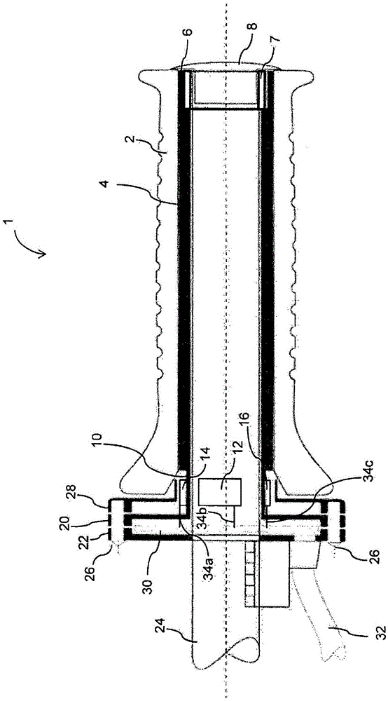
[0028] refer to figure 1 , figure 1 A sectional view showing the guide bar and the control handle 1 of the vehicle. The control handle 1 includes a hand glue 2 and a grip tube 4 . The hand glue 2 and the grip tube 4 constitute a grip area. Drivers of vehicles such as motorcycles, tricycles, quads, snowmobiles, jet skis, etc. are used to hold the hand gel 2 . The hand glue 2 is rigidly connected with the grip tube 4 . To control the speed, the driver applies torque to the grip tube 4 via the grip area 2 .

[0029] The grip tube 4 is connected rigidly and non-rotatably to a link 24 of the vehicle via the detection region 10 and the control handle-side mounting region 20 and the link-side mounting region 22 . The torque exerted by the driver causes a twist in the gripping tube 4 , in the detection region 10 , in the installation regions 20 , 22 and in the link 24 , since the gripping regions 2 , 4 are rigidly connected to the link 24 . Since the detection region 10 is confi...


PUM


Abstract

The invention discloses a control grip, for example a throttle grip, which is designed to control the speed of a vehicle on the basis of an axial torque which is applied to the control grip, comprising a holding region which is designed to be held by the hand of a user, and having a fitting region which is designed to fit the holding region to a component of the vehicle such that it cannot axially rotate, wherein the acceleration and / or the speed of the vehicle depends on the axial torque which is applied to the holding region by the user, characterized in that the holding region and the fitting region are connected to one another in a rigid manner or such that they cannot rotate.

Description

technical field [0001] The present invention relates to a control handle for a vehicle, wherein the speed and / or deceleration of the vehicle can be controlled by torque applied to the control handle. This handle is also known as the throttle handle. Background technique [0002] In two-, three- or four-wheeled vehicles such as motorcycles, tricycles, four-wheelers, snowmobiles and watercraft such as jet skis, a so-called throttle handle is usually arranged on the guide rod, which is formed as a rotary handle and controls the The power output of an internal combustion engine. Power output is achieved by axially turning the so-called throttle grip. Power output is traditionally controlled by a rope-pull mechanism from the throttle grip to the carburetor. In the early days electric throttle grips were used, wherein the axial rotational movement of the throttle grip was used to control acceleration. The signal from this electric throttle grip is forwarded to the electronic m...

Claims


Application Information

Patent Timeline
Patent Type & Authority Applications(China)
IPC IPC(8): B62K23/04
CPCB62K23/04
Inventor S·奥古斯丁
Owner BAYERISCHE MOTOREN WERKE AG
Why Eureka
Try Eureka