
Rail fastening point and base plate for such a rail fastening point

A technology for fixing points and tracks, applied in the direction of fixing rails, tracks, roads, etc., can solve the problem of expensive manufacturing technology, and achieve the effect of easy installation, light weight and less material consumption.

Active Publication Date: 2016-04-13
VOSSLOH WERKE GMBH
View PDF8 Cites 0 Cited by
  • Summary
  • Abstract
  • Description
  • Claims
  • Application Information

AI Technical Summary

Problems solved by technology

However, this arrangement is rather expensive in terms of production technology, since different inclinations of the rail have to be realized for curves of different curvature

Method used


Image

  • Rail fastening point and base plate for such a rail fastening point
  • Rail fastening point and base plate for such a rail fastening point
  • Rail fastening point and base plate for such a rail fastening point

Examples


Embodiment Construction

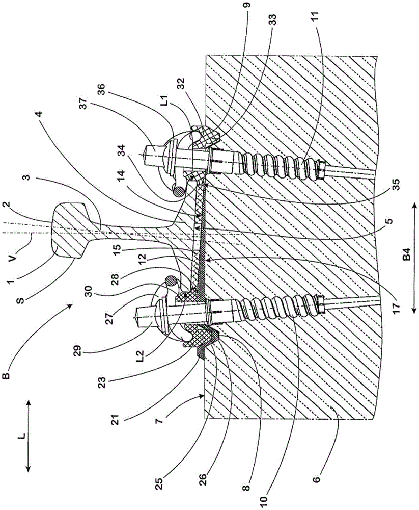
[0041] Track S is fixed on the attached figure 1 On the rail fixing point B shown in , it generally has: a rail head 1, on the upper side of which is formed a running surface 2 for rail wheels (also not shown) of a rail vehicle (not shown); A rail web 3 supporting the rail head 1; and a rail base 4, which is arranged at the center of the rail base. The rail base 4 is wider than the rail head 1 and has a flat support surface 5 on its underside.

[0042] The track fixing point B comprises a foundation 6 which in the present embodiment is formed by a conventional type of sleeper cast in concrete. On its upper side, the foundation 6 has a flat contact surface 7 which extends over the length of the foundation 6 measured in a foundation longitudinal direction L aligned transversely to the rail S. As shown in FIG.

[0043] Two groove-like recesses 8 , 9 are formed at a distance from one another on the contact surface 7 , which extend parallel to each other and to the longitudinal e...


PUM


Abstract

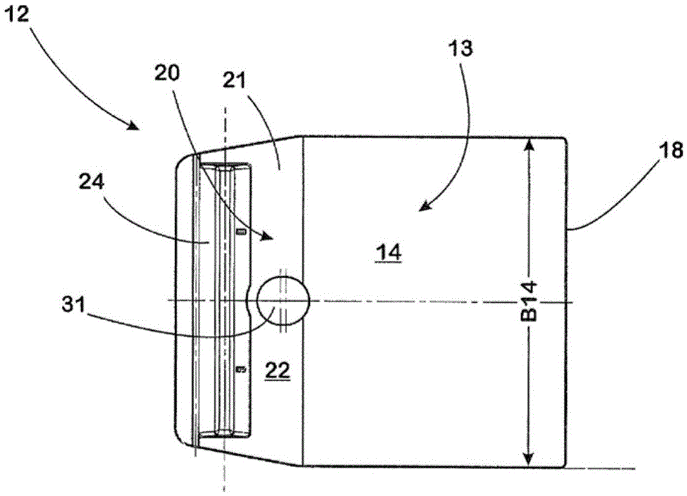
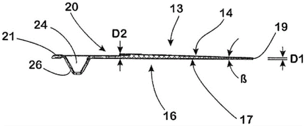
The invention relates to a rail fastening point for a rail (S) for a rail vehicle on a foundation (6), comprising two guide plates (23, 32), each guide plate (23, 32) being paired with one of the longitudinal sides (L1, L2) of the rail (S), and a base plate (12) which is arranged between the foundation (6) and the rail (S). The base plate (12) has a support surface (14), on which the rail (S) is supported in the installed state, on the base plate upper face (13) and a bearing surface, via which the base plate (12) is supported on the foundation (6) in the installed state, on the base plate lower face. The support surface and the bearing surface of the base plate (12) form an acute angle (beta) between each other when seen in a section arranged transversely to the longitudinal extension of the rail (S).

Description

technical field [0001] The invention relates to a rail fastening point at which a rail for a rail vehicle is fastened to a foundation. In such fastening points, the rail to be fastened generally has a rail head on whose upper side the running surface of the rail wheels of the rail vehicle is formed, a rail web supporting the rail head, and a rail foot, viewed in cross section , the rail bottom is obviously wider than the rail head and the rail web, and the rail web stands on the rail bottom. In the installed position, the rail rests with the rail base on the respective foundation, wherein various layers can be arranged between the rail and the foundation in order to achieve contact between the rail and the foundation. Background technique [0002] This makes it possible to arrange a plate-shaped intermediate layer between the rail base and the foundation, made of a material with precisely defined elasticity, and to ensure that the rail is elastically depressed when the vehi...

Claims


Application Information

Patent Timeline
Patent Type & Authority Applications(China)
IPC IPC(8): E01B9/68
CPCE01B9/685E01B9/68E01B9/40
Inventor 安德烈·胡诺尔德温弗里德·博斯特林
Owner VOSSLOH WERKE GMBH
Learn More