Puncture enhancing method and system

A technology for enhancing systems and puncture needles, applied in the fields of puncture needles, medical science, acoustic wave diagnosis, etc., which can solve the problems of decreased flexibility, increased operational complexity, and difficulty in accurately judging the insertion angle of the puncture needle, and achieves an enhanced display effect. , the effect of improving flexibility and reducing complexity

Active Publication Date: 2016-04-20
SHENZHEN WISONIC MEDICAL TECH CO LTD
View PDF6 Cites 23 Cited by
  • Summary
  • Abstract
  • Description
  • Claims
  • Application Information

AI Technical Summary

Problems solved by technology

Although the operator is the user himself, it is difficult for the general operator to accurately judge the insertion angle of the puncture needle. At the same time, since the puncture needle cannot always maintain a constant puncture angle during operation, it is difficult for the user to determine the ultrasonic probe during the puncture process. The optimal large deflection angle of the puncture needle, and thus the display effect of the puncture needle image is often not as perfect as designed. Although the puncture frame can be used to limit the insertion direction of the puncture needle, this will greatly reduce the flexibility of the doctor's surgical process. And if the angle needs to be adjusted continuously during the operation, it will increase the complexity of the operation

Method used


Image

  • Puncture enhancing method and system
  • Puncture enhancing method and system
  • Puncture enhancing method and system

Examples


Embodiment Construction

[0048] It should be understood that the specific embodiments described here are only used to explain the present invention, not to limit the present invention.

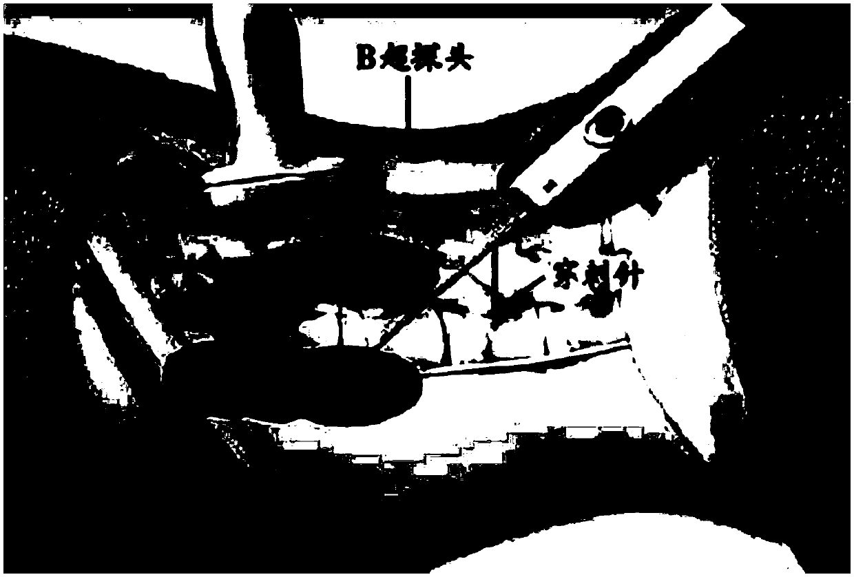
[0049] As we all know, when ultrasonic imaging is performed in conventional B-ultrasound mode, the smooth surface of the puncture needle will cause the mirror reflection of the needle body, which will cause the ultrasonic echo of the needle body part to be too weak, thus making the display visibility of the puncture needle in the ultrasound image If it is too low, it is not conducive for doctors to perform puncture operations with reference to ultrasound images. Therefore, it is necessary to enhance the display effect of the puncture needle in the ultrasonic image to improve the visibility of the puncture needle.

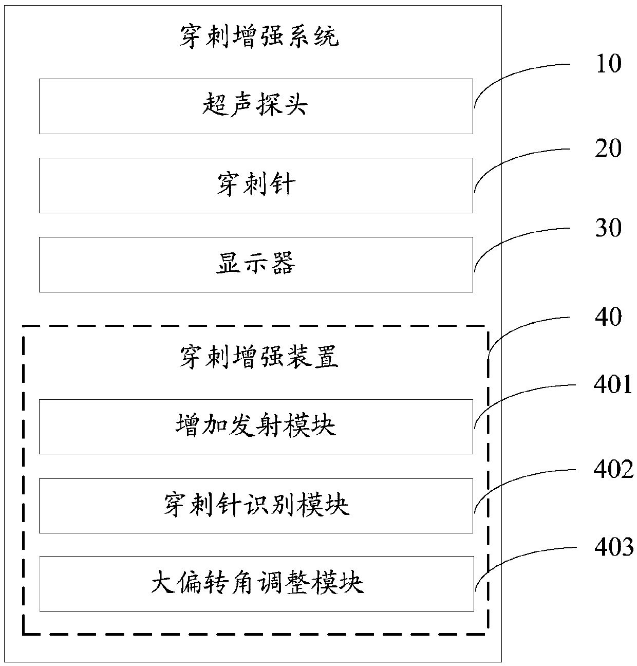
[0050] The present invention provides a puncture enhancement system.

[0051] refer to figure 1 , figure 1 It is a schematic diagram of functional modules of an embodiment of the puncture enhancement syste...


PUM


Abstract

The invention discloses a puncture enhancing method. The method comprises the steps that when an ultrasonic probe transmits ultrasonic waves with a large deflection angle for scanning in this cycle so as to display a puncture needle image in an enhanced mode, ultrasonic waves with different transmitting angles and a specific waveform are transmitted for scanning; the insertion orientation of a puncture needle is identified according to scanned image frame data corresponding to the ultrasonic waves with the specific waveform at different transmitting angles; a corresponding large deflection angle when the ultrasonic probe transmits ultrasonic waves with the large deflection angle in a next cycle is adjusted according to the identified insertion orientation of the puncture needle, and the transmitting direction of the ultrasonic waves is perpendicular to or approximately perpendicular to the identified insertion orientation of the puncture needle under the large deflection angle. The invention further discloses a puncture enhancing system. By means of the puncture enhancing method and system, the insertion orientation of the puncture needle can be rapidly detected, and therefore the insertion direction of the puncture needle does not need to be fixed. Meanwhile, the complexity of puncture enhancing manipulation is reduced by automatically adjusting the large deflection angle of the ultrasonic probe, and the optimal display effect of the puncture enhancing image is always maintained.

Description

technical field [0001] The invention relates to the technical field of ultrasonic imaging, in particular to a puncture enhancement method and system. Background technique [0002] Puncture enhancement technology is now widely used in medical ultrasound practice to guide doctors to perform puncture operations and improve surgical efficiency and safety. At present, the main working method of the puncture enhancement technology is to appropriately enhance the area of ​​the puncture needle by using specially matched hardware and software algorithms to improve the visibility. In the prior art, it is usually necessary to add a frame of ultrasonic images formed by transmitting ultrasonic waves at a large deflection angle of the probe to ensure that the ultrasonic emission direction is as perpendicular as possible to the puncture needle body (at this time, the echo reflection effect of the puncture needle body is the best) . Generally speaking, the deflection angle of the probe wi...

Claims


Application Information

Patent Timeline
Patent Type & Authority Applications(China)
IPC IPC(8): A61B17/34
CPCA61B8/00A61B17/34A61B2017/3413
Inventor 黄灿朱利华姚斌李瑞军
Owner SHENZHEN WISONIC MEDICAL TECH CO LTD
Why Eureka
Try Eureka