
Bracket positioning frame and manufacturing method of bracket positioning frame

A positioning frame and bracket technology, which is applied in the manufacturing field of bracket positioning frame and bracket positioning frame, can solve the problems that hinder the popularization and application of indirect bonding technology, the difficulty of removing the transfer tray, and the difficulty of removing the adhesive, etc., to achieve Repeatable and accurate secondary bonding, improved operating efficiency and simplicity, and reduced use of consumables

Active Publication Date: 2016-04-20
万正(无锡)智能科技有限公司
View PDF6 Cites 48 Cited by
  • Summary
  • Abstract
  • Description
  • Claims
  • Application Information

AI Technical Summary

Problems solved by technology

The existing indirect bonding technology has significantly improved the accuracy of bracket bonding, but because it has a large number of complicated laboratory preparation procedures, the bonding positioning on the model still depends on experience, and the clinical operation requires a certain learning cost. Ensuring that each bracket is subjected to uniform and sufficient positive pressure may result in an excessively thick and variable adhesive layer between the bracket base and the tooth surface, adhesive spills under the cover of the coated transfer tray are difficult to remove, The existence of problems such as the relative difficulty of removing the transfer tray hinders the promotion and application of indirect bonding technology

Method used


Image

  • Bracket positioning frame and manufacturing method of bracket positioning frame
  • Bracket positioning frame and manufacturing method of bracket positioning frame
  • Bracket positioning frame and manufacturing method of bracket positioning frame

Examples


Embodiment Construction

[0038] In order to make the object, technical solution and advantages of the present invention clearer, various embodiments of the present invention will be described in detail below in conjunction with the accompanying drawings. However, those of ordinary skill in the art can understand that, in each implementation manner of the present invention, many technical details are provided for readers to better understand the present application. However, even without these technical details and various changes and modifications based on the following implementation modes, the technical solution claimed in each claim of the present application can be realized.

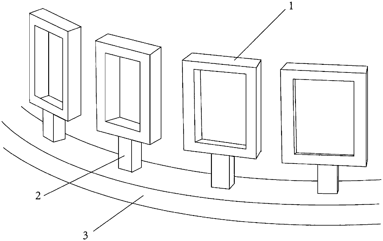
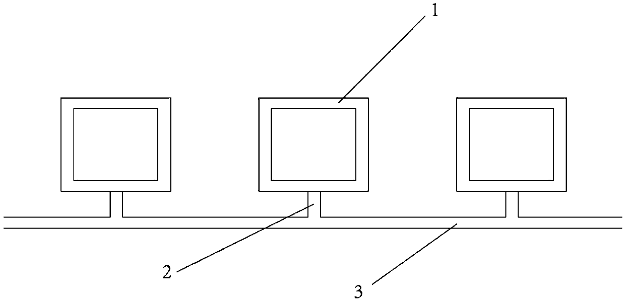
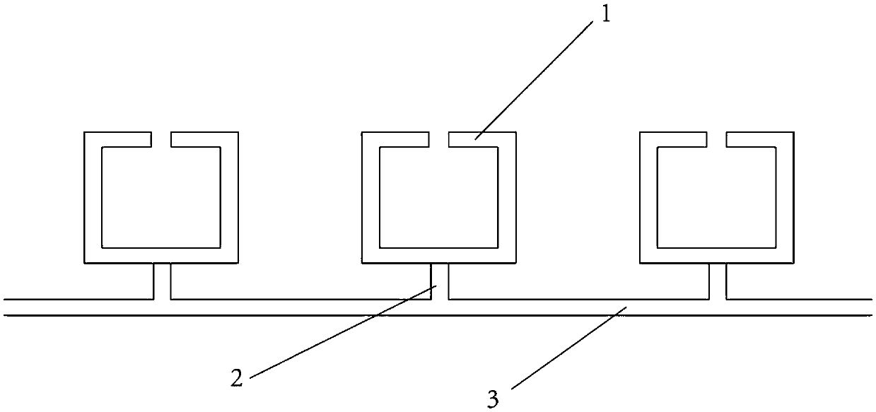
[0039] The first embodiment of the present invention relates to a bracket 4 positioning frame for positioning the bracket 4, see figure 1 and figure 2 As shown, it includes several fixing frames 1 arranged around the periphery of the bracket 4 , the shape of the inner frame of the fixing frame 1 is adapted to the shape of ...


PUM


Abstract

The invention relates to the technical field of medical equipment, and discloses a bracket positioning frame and a manufacturing method of the bracket positioning frame. The bracket positioning frame is used for positioning a bracket and comprises a plurality of fixed frames and a support mechanism, wherein the fixed frames are arranged around the periphery of the bracket; the inner frame shapes of the fixed frames are matched with the outline shape of the bracket; the bracket is fixed in the fixed frames; the fixed frames are assembled on the support mechanism; the shape of the support mechanism is matched with the anatomical shape of the part, contacting the support mechanism, in an oral cavity of a patient; and the fixed frames correspond to teeth one by one. The bracket positioning frame can provide a very accurate bracket bonding position under the premise of not changing the traditional direct bonding habit of an orthodontist, and is simple to disassemble and assemble and low in cost. According to the manufacturing method of the bracket positioning frame, personalized customization of the bracket positioning frame can be conveniently carried out according to the dentition of the patient; the design and manufacturing processes are completely digitized; and the accuracy, the repeatability and the feasibility all are very ideal.

Description

technical field [0001] The invention relates to the technical field of medical equipment, in particular to a bracket positioning frame and a manufacturing method of the bracket positioning frame. Background technique [0002] In orthodontic treatment, the most important treatment method is fixed orthodontics. The fixed appliance system mainly consists of arch wires and orthodontic brackets. The brackets are bonded to the surface of the teeth with light-curing adhesives, accommodate and fix the archwires, transmit the orthodontic force generated by the archwires to the teeth, and make the teeth arrange and move along the archwires, so as to achieve the purpose of orthodontics. In contemporary orthodontics, the accuracy of bracket bonding is an important prerequisite to ensure the ideal result of orthodontic treatment. [0003] In current orthodontic treatment, direct bonding is usually used when bonding brackets to tooth surfaces. Since the existing direct bonding technolo...

Claims


Application Information

Patent Timeline
IPC IPC(8): A61C7/14A61C7/16
CPCA61C7/146A61C7/16
Inventor 张哲谌余佳梦沈刚钱玉芬
Owner 万正(无锡)智能科技有限公司
Learn More