Purifying separator

A purification separation and controller technology, which is applied in separation methods, dispersed particle separation, chemical instruments and methods, etc., can solve the problems of lower production efficiency, increased maintenance workload, and decreased filtration performance, so as to ensure filtration performance and reduce maintenance. Work load, productivity improvement effect

Inactive Publication Date: 2016-04-20
广州市白云华申空压机厂
View PDF8 Cites 14 Cited by
  • Summary
  • Abstract
  • Description
  • Claims
  • Application Information

AI Technical Summary

Problems solved by technology

[0002] At present, the produced coal gas, biomass vaporized gas or mined coalbed methane all contain dust impurities, coal tar, free water and other substances, which need to be purified through a gas separation filter before use. The existing gas separation filter, Including the tank body, the clapboard set in the tank body, the air inlet set on the side wall of the tank body below the clapboard, the exhaust port set on the tank body above the clapboard, the slag discharge port set at the bottom of the tank body, Several filter elements are arranged at the lower end of the partition. When in use, the gas enters from the air inlet, flows upwards and is filtered by the filter elements, and then is discharged from the exhaust port. During this process, because the gas directly flows upwards and contacts the filter elements, It absorbs a large amount of heavy impurities such as dust and free water, and is easy to be blocked, resulting in a rapid decline in its filtration performance. The filter element needs to be cleaned frequently, which not only increases the maintenance workload, but also affects the continuity of production and reduces production efficiency.

Method used


Image

  • Purifying separator

Examples


Embodiment Construction

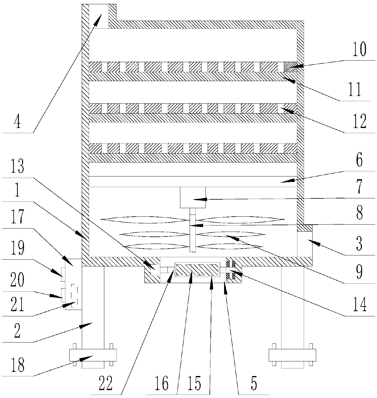
[0017] The present invention is specifically described below in conjunction with accompanying drawing, as figure 1 As shown, a purifying separator comprises a rectangular box (1), the four corners of the bottom of the rectangular box (1) are provided with columns (2), and the outer surface of the lower end of the rectangular box (1) is provided with There is an air inlet (3), the upper surface of the rectangular box (1) is provided with an air outlet (4), the lower surface of the rectangular box (1) is provided with a slag outlet (5), and the rectangular box (1) is provided with a slag outlet (5). The box body (1) is provided with a crossbeam (6), on which a motor (7) is fixedly installed, and a vertical rotating shaft (8) is fixedly connected to the rotating end of the motor (7), so that Multi-layer blades (9) are fixedly set on the rotating shaft (8), and the rectangular box (1) at the upper end of the beam (6) is provided with multi-layer partitions (10), and each layer of ...


PUM


Abstract

The invention discloses a purifying separator. The purifying separator comprises a rectangular box, stand columns are arranged at the four corners of the bottom of the rectangular box, an air inlet is formed in the outer side surface of the lower end of the rectangular box, an air outlet is formed in the upper surface of the rectangular box, and a residue discharge port is formed in the lower surface of the rectangular box; a beam is arranged in the rectangular box, a motor is fixedly installed on the beam, a vertical rotating shaft is fixedly connected with a rotating end of the motor and fixedly sleeved with multiple layers of blades, multiple partition plates are arranged on the portion, located at the upper end of the beam, in the rectangular box, an active carbon layer is arranged on the lower surface of each partition plate, and multiple through holes are uniformly distributed in each partition plate; a tiny metal sorting and collecting mechanism is arranged in the residue discharge port, and a controller is arranged on the outer surface of the rectangular box. The purifying separator has the advantages of being simple in structure and high in practicability.

Description

technical field [0001] The invention relates to a filtering and purifying device, in particular to a purifying separator. Background technique [0002] At present, the produced coal gas, biomass vaporized gas or mined coalbed methane all contain dust impurities, coal tar, free water and other substances, which need to be purified through a gas separation filter before use. The existing gas separation filter, Including the tank body, the clapboard set in the tank body, the air inlet set on the side wall of the tank body below the clapboard, the exhaust port set on the tank body above the clapboard, the slag discharge port set at the bottom of the tank body, Several filter elements are arranged at the lower end of the partition. When in use, the gas enters from the air inlet, flows upwards and is filtered by the filter elements, and then is discharged from the exhaust port. During this process, because the gas directly flows upwards and contacts the filter elements, It absorb...

Claims


Application Information

Patent Timeline
Patent Type & Authority Applications(China)
IPC IPC(8): B01D50/00B01D53/06C10L3/10C10K1/02
CPCB01D50/00B01D53/06B01D2253/102C10K1/02C10L3/101
Inventor 吴倩倩
Owner 广州市白云华申空压机厂
Why Eureka
Try Eureka