Ultrasonic cutter head for machining small holes and application of ultrasonic cutter head

An ultrasonic and tool head technology, which is applied to tools for lathes, manufacturing tools, metal processing equipment, etc., can solve the problems of inability to process tiny inner holes and inner holes, so as to reduce the structural size and avoid uncertain directions. , the effect of preventing rotation

Active Publication Date: 2016-04-20
SHANDONG HUAWIN ELECTRICAL & MECHANICAL TECH
View PDF6 Cites 4 Cited by
  • Summary
  • Abstract
  • Description
  • Claims
  • Application Information

AI Technical Summary

Problems solved by technology

The tool can extend into the inner hole, and can perform ultrasonic machining on the side wall of the inner hole, but the ultrasonic tool can only process inner holes with a diameter of more than 30mm, and cannot process inner holes with a diameter of less than 30mm
[0004] Therefore, there is an urgent need to design an improved ultrasonic machining tool head to solve the problem of inability to process tiny inner holes

Method used


Image

  • Ultrasonic cutter head for machining small holes and application of ultrasonic cutter head
  • Ultrasonic cutter head for machining small holes and application of ultrasonic cutter head
  • Ultrasonic cutter head for machining small holes and application of ultrasonic cutter head

Examples


Embodiment 1

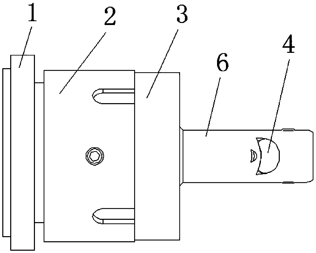
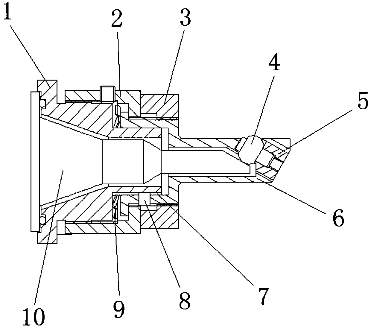
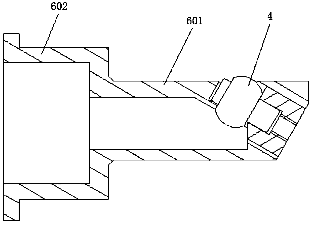
[0028] Such as Figure 1 to Figure 3 As shown, an ultrasonic tool head for processing small holes, the ultrasonic tool head includes a horn 10, a taper sleeve 1, a tool seat 6, a tool head 4 and an adjustment ring 2; The seat 6 is connected, and the adjustment ring 2 is a hollow cylinder with an internal thread at the end. The internal thread at the end of the adjustment ring is connected with the external thread at the front end of the taper sleeve, and the front end of the adjustment ring 2 is clamped with the tool seat 6. , the tool head 4 is embedded in the front end of the tool seat 6 and fixed by the positioning block 5. The horn sleeve 1 is provided with an inner hole for accommodating the horn, and the horn 10 extends into the taper sleeve 1 and the tool seat 6. The horn The front end of the tool head is set as a slope structure, and the outer circular surface of the tool head 4 is in vertical contact with the slope structure.

[0029] Specifically, the tool seat 6 in...

Embodiment 2

[0032] An ultrasonic tool head for machining small holes, the structure is as described in Embodiment 1, the difference is that a wave spring 9 is placed in the gap between the taper sleeve 1 and the tool seat 6 . On the one hand, the wave spring 9 can support the tool seat, so that the tool seat and the front end of the taper sleeve are clamped more firmly, and on the other hand, when adjusting the gap between the horn and the tool head, accurate fine adjustment can be achieved. The front end of the horn 10 is arranged in a spherical structure, and the outer circular surface of the tool head 4 is in vertical contact with the spherical structure.

Embodiment 3

[0034] An ultrasonic tool head for processing small holes, the structure of which is as described in Embodiment 1, the difference is that a locking ring 3 is also provided on the tool seat 6, and the locking ring 3 is threadedly connected with the tool seat 6 and is located in the adjustment ring 2 sides. When the adjusting ring is adjusted to a proper position, lock the adjusting ring through the locking ring.


PUM


Abstract

The invention relates to an ultrasonic cutter head for machining small holes and an application of the ultrasonic cutter head. The ultrasonic cutter head comprises a variable-amplitude bar, a taper sleeve, a tool seat, a tool head and an adjusting ring, wherein the taper sleeve is connected with the tool seat by the aid of the adjusting ring, the tool seat is step-shaped, the tool head is arranged at the front end of the tool seat, the variable-amplitude bar extends into the taper sleeve and the tool seat, and the tool head is perpendicularly contacted with the front end of the variable-amplitude bar. According to the ultrasonic cutter head, the structural form of the tool seat is improved, the overall structure size of the tool seat is reduced, the ultrasonic cutter head can be used for machining inner holes with diameters smaller than 30 mm, and the machining range of the ultrasonic cutter head is wider. Meanwhile, the taper sleeve and the tool seat are in guided connection by the aid of a key or a pin, the tool seat can be effectively prevented from rotating when the clearance between the variable-amplitude bar and the tool head is adjusted, and the problem that the direction of the tool head is not determined due to rotation of the tool seat is solved.

Description

technical field [0001] The invention relates to an ultrasonic cutter head for processing small holes and an application thereof, belonging to the technical field of ultrasonic processing. Background technique [0002] At present, the use of ultrasonic machining in the field of mechanical processing has been relatively mature, and ultrasonic tools are the most important part of the ultrasonic machining process. For example, using ultrasonic tools to process the inner surface of the inner hole can well reduce the surface roughness of the inner hole , but because the current ultrasonic tool needs to extend the ultrasonic tool head into the inner hole when processing the inner hole, it is more convenient to process the inner hole with a larger diameter, but when the hole diameter is less than 30mm, the existing ultrasonic tool head The structural size makes it impossible to extend into the inner hole for ultrasonic processing. [0003] For example, Chinese patent document CN204...

Claims


Application Information

Patent Timeline
Patent Type & Authority Applications(China)
IPC IPC(8): B23B27/00
CPCB23B27/007
Inventor 柏士增赵显华谢祥科刘秀娟赵志明
Owner SHANDONG HUAWIN ELECTRICAL & MECHANICAL TECH
Why Eureka
Try Eureka