
A shape forming knife

A technology of forming knives and appearance, which is applied in the direction of milling cutters, manufacturing tools, metal processing equipment, etc., can solve the problems of multiple tool replacements, and achieve the effects of reducing safety hazards, low production costs, and simple use

Inactive Publication Date: 2018-04-17
ZHONGSHAN YUANFENG PRECISION CUTTING TOOL CO LTD
View PDF9 Cites 0 Cited by
  • Summary
  • Abstract
  • Description
  • Claims
  • Application Information

AI Technical Summary

Problems solved by technology

[0003] In order to solve the problem that the cutting tool needs to be replaced many times when the general milling machine processes irregular parts, the present invention proposes an appearance shaping knife

Method used


Image

  • A shape forming knife
  • A shape forming knife
  • A shape forming knife

Examples


Embodiment Construction

[0018] Embodiments of the present invention are described in detail below, examples of which are shown in the drawings, wherein the same or similar reference numerals represent the same or similar elements or elements having the same or similar functions throughout.

[0019] In the description of the present invention, it should be noted that for orientation words, such as the term "center", "horizontal (X)", "longitudinal (Y)", "vertical (Z)", "length", "width ", "Thickness", "Top", "Down", "Front", "Back", "Left", "Right", "Vertical", "Horizontal", "Top", "Bottom", "Inner" , "Outside", "Clockwise", "Counterclockwise", etc. indicating orientation and positional relationship are based on the orientation or positional relationship shown in the drawings, and are only for the convenience of describing the present invention and simplifying the description, rather than indicating or implying The devices or elements must have a specific orientation, be constructed and operated in a ...


PUM


Abstract

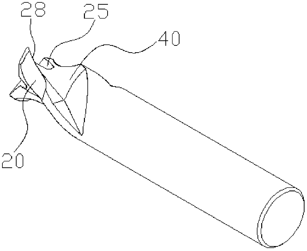
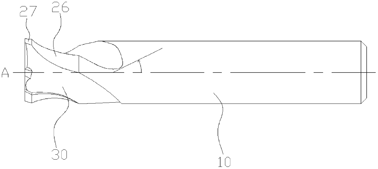
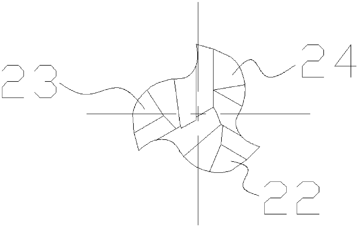
The invention discloses an appearance forming cutter which comprises a cutter body and one or more cutting seats formed at the top end of the cutter body. The cutting seats are twisted rightwards with the longitudinal central axis as a reference axis. Chip guide grooves are formed between the adjacent cutting seats and connected with the adjacent cutting seats in a smooth mode. Concave positions are formed in the tops of the cutting seats and are formed in the parts close to the longitudinal central axis. The cutting seats are provided with twisted arc surfaces and cutting planes, wherein the cutting planes are located at the tops of the cutting seats and connected with the twisted arc surfaces, the twisted arc surfaces are tangent to the side parts of the cutting seats to form cutting edges, and the length of the twisted arc surfaces is smaller than the length of the cutting seats. The appearance forming cutter has the advantages of being simple in structure, convenient to machine and low in production cost; it is avoided that cutters are changed many times when non-standard parts are machined, and the potential safety hazards caused when the cutters are changed are reduced.

Description

【Technical field】 [0001] The invention mainly relates to an appearance shaping knife. 【Background technique】 [0002] A cutting tool is a tool used for cutting in mechanical manufacturing, also known as a cutting tool. The vast majority of knives are for machine use, but some are also for hand use. Since the knives used in mechanical manufacturing are basically used to cut metal materials, the term "knife" is generally understood as a metal cutting tool. In mechanical manufacturing such as milling machines, the tool generates a lot of heat when cutting, and it is very troublesome to replace the tool, or in the process of changing the tool, once the operation is wrong, it is very easy to cause work injury. Generally, the milling machine is a three-axis processing machine tool, and most of the workpieces in the milling process of the machine tool are standard and regular shapes, which will make the processing convenient. However, milling machines often need to process many ...

Claims


Application Information

Patent Timeline
Patent Type & Authority Patents(China)
IPC IPC(8): B23C5/00B23C5/12
CPCB23C5/00B23C5/12B23C2210/40
Inventor 朱松林廖志雄
Owner ZHONGSHAN YUANFENG PRECISION CUTTING TOOL CO LTD
Learn More