Explosive welding support device and application thereof

A support device and explosive welding technology, which is applied in welding equipment, welding/welding/cutting items, non-electric welding equipment, etc., can solve the problems that the support body is not easy to pull out, the support body should not be too long, and the position of the double board can move, etc., to achieve Improve hoisting efficiency and improve the effect of easy and difficult to put

Inactive Publication Date: 2016-04-20
HUBEI JINLAN SPECIAL METAL MATERIAL
View PDF9 Cites 0 Cited by
  • Summary
  • Abstract
  • Description
  • Claims
  • Application Information

AI Technical Summary

Problems solved by technology

However, the traditional method has its limitations, especially when the board width is large, because the stress point of the doubler board is at the edge during the hoisting process, the board surface is bent, and the traditional wooden strips, bamboo chips and other protective gap supports The support body should not be too long. If the length is not enough, the gap support body in the middle part will not be protected due to the bending of the board surface, and the gap support body in the middle part will collapse.
However, if the support is too long, it will be difficult to pull out the support due to the weight of the doubler board. Pulling out forcibly will easily cause the position of the doubler board to move around or even cause a large gap in the support body to collapse, which will affect the composite quality.

Method used


Image

  • Explosive welding support device and application thereof
  • Explosive welding support device and application thereof
  • Explosive welding support device and application thereof

Examples


Embodiment Construction

[0025] The present invention will be further described below in conjunction with the examples, but the protection scope of the present invention is not limited only to the examples.

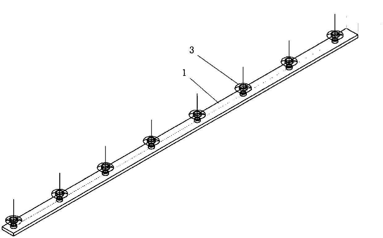
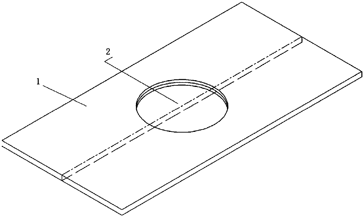
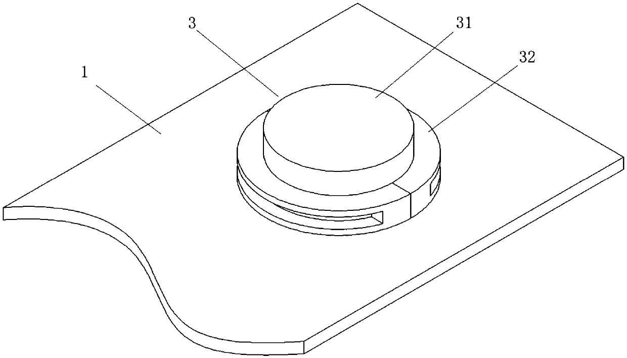
[0026] Such as figure 1 , figure 2 , image 3 , Figure 4 , Figure 5 and Figure 6 As shown, an explosive welding support device has a strip-shaped base 1 with a thickness of about 2mm and an overall length of about 1.5m. . A plurality of threaded holes 2 are arranged side by side on the base 1, and a support member 3 is threadedly connected to the threaded holes 2. The support member 3 includes a lower support member 32 and an upper support member 31; the lower support member 32 is a ring structure, and the inside is a hole , the lower supporting part 3 includes a circular ring structure 321 and a limiting ring 322 arranged on the upper end of the circular ring structure 321 , the inner diameter of the limiting ring 322 is smaller than the inner diameter of the circular ring structure 32...


PUM


Abstract

The invention discloses an explosive welding support device and application thereof. The explosive welding support device has a base which is provided with a threaded hole which is in threaded connection with a support part, and the support part comprises a lower support part and an upper support part; the lower support part comprises a circular structure and a limiting ring disposed at an upper end of the circular structure, and the inner diameter of the limiting ring is less than that of the circular structure; the upper support part comprises a cylindrical structure and a limiting step disposed at the lower end of the cylindrical structure, the diameter of the limiting step is greater than that of the cylindrical structure, and the limiting step is disposed inside the lower support part; the outer wall of the lower support part is provided with an external thread. The explosive welding support device has the advantages that the problem that a middle part of a gap support cannot gain good protection due to the inability of the traditional support to be extra-long is avoided; the problem that the traditional support is 'easy to place but difficult to pick' is improved, and lifting efficiency is improved; the support part is a replaceable part, applicable to protecting gap supports of different heights, and the problem that an overall assembly is unavailable for use due to damage to certain parts is also avoided.

Description

technical field [0001] The invention relates to the technical field related to metal explosive welding, in particular to an explosive welding support device for protecting a gap support body during explosive welding of a composite plate and its application. Background technique [0002] Explosive metal welding is an edge subject between metal physics, explosion physics and welding technology. It belongs to a new high-tech. It has unique technology and broad market application prospects. Explosive welding technology can perfectly realize the metallurgical combination of different metal materials with extremely different properties. The obtained new composite material integrates the advantages of two or more materials, and can give full play to the properties of different metal materials in the composite material. The use of rare precious metal materials is reduced, but the advantages of precious metals are guaranteed to be reflected, and the manufacturing cost of equipment i...

Claims


Application Information

Patent Timeline
IPC IPC(8): B23K20/08B23K20/26B23K101/18
CPCB23K20/08B23K20/26B23K2101/18
Inventor 铀铀周佐玉王雄王道阳朱丽丽
Owner HUBEI JINLAN SPECIAL METAL MATERIAL
Why Eureka
Try Eureka