High-speed drilling and milling center

A machining center, drilling and milling technology, applied in the direction of metal processing equipment, metal processing machinery parts, manufacturing tools, etc., can solve the problems of low machine tool processing efficiency and occupation of machine tool processing time, so as to increase the weight of machinable workpieces and improve the processing efficiency. Efficiency, the effect of reducing deformation

Inactive Publication Date: 2016-04-20
嘉泰数控科技股份公司
View PDF13 Cites 8 Cited by
  • Summary
  • Abstract
  • Description
  • Claims
  • Application Information

AI Technical Summary

Problems solved by technology

[0002] The existing drilling and milling machining centers usually have a single workbench structure. The auxiliary actions of clamping and dismounting the workpiece on the workbench greatly occupy the processing time of the machine tool, and the processing efficiency of the machine tool is not high.

Method used


Image

  • High-speed drilling and milling center
  • High-speed drilling and milling center
  • High-speed drilling and milling center

Examples


Embodiment Construction

[0020] The present invention will be further described below in conjunction with the accompanying drawings and specific embodiments.

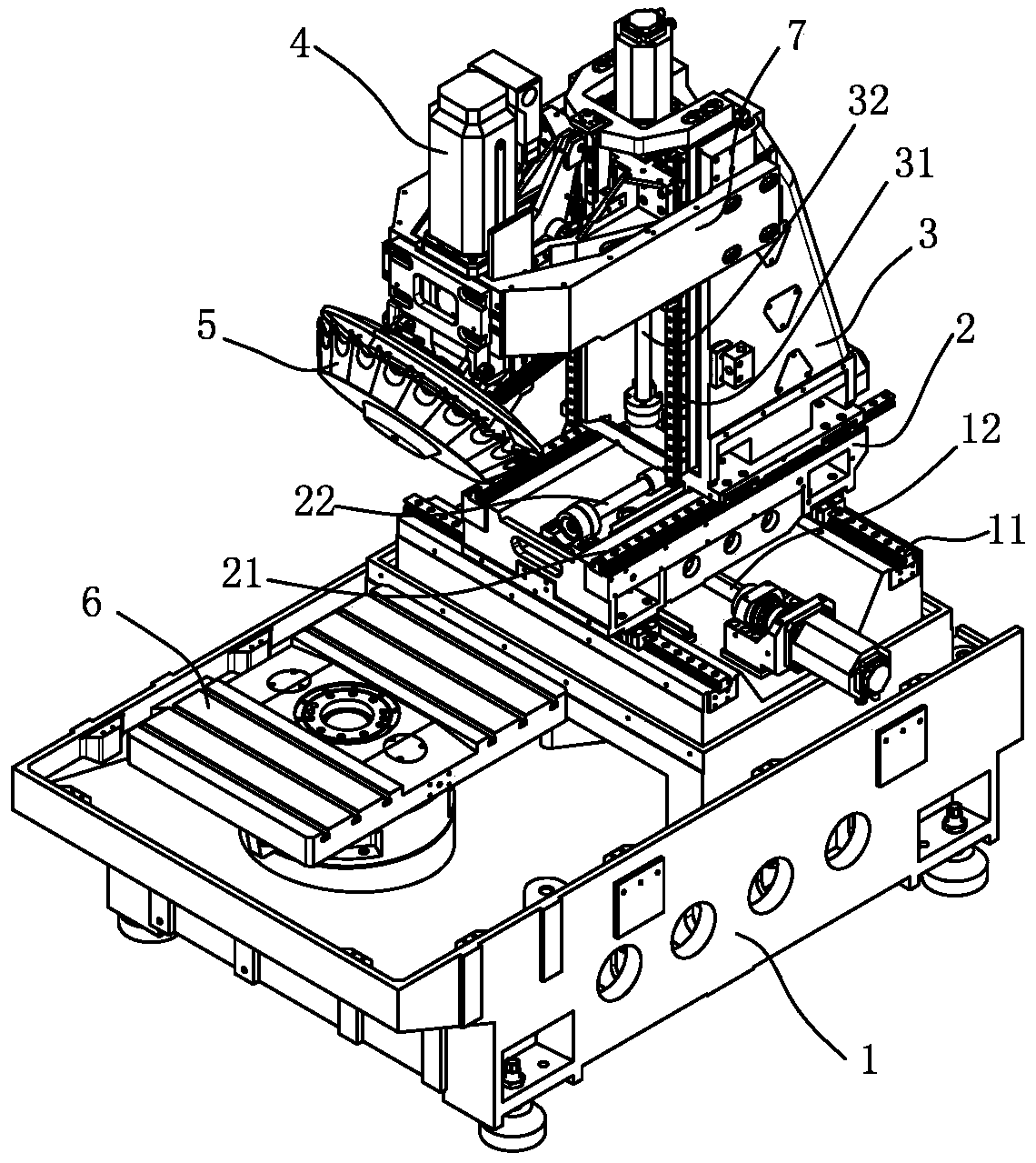
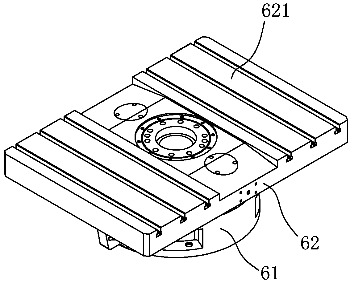
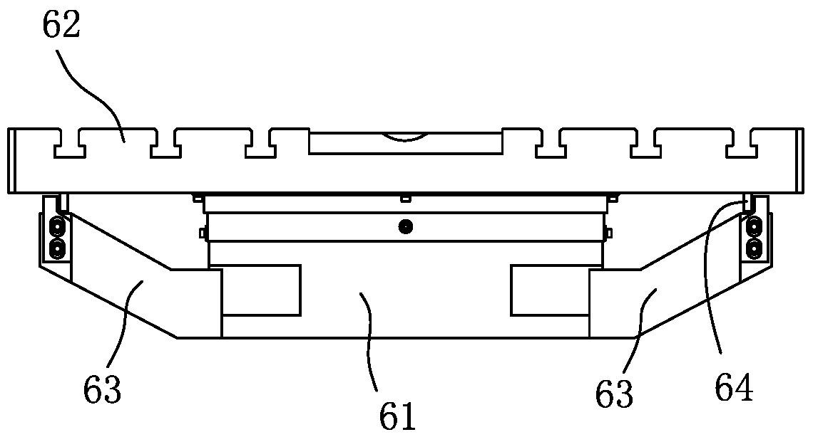
[0021] Such as Figure 1-Figure 8 As shown, the high-speed drilling and milling machining center of the present invention includes a spindle box 4, an exchange table 6, a base 1 provided with an X-guiding rail 11, a saddle 2 provided with a Y-guiding rail 21, and a column provided with a Z-guiding rail 31 3. The saddle 2 is slidably arranged on the X-guiding rail 11, and there is a lead screw pair 12 in the X direction that drives the saddle 2 to slide between the saddle 2 and the base 1; the column 3 is slidably arranged in the Y direction On the guide rail 21, between the column 3 and the saddle 2, there is a Y-direction screw pair 22 that drives the column 3 to slide; There is a Z-direction lead screw pair 32 that drives the headstock 4 to slide; the exchange table 6 is arranged on the base 1, and the exchange table 6 includes a workbench b...


PUM


Abstract

The invention provides a high-speed drilling and milling center which comprises a spindle box, a pallet changer, a base provided with an X-direction guide rail, a carriage provided with a Y-direction guide rail and a stand column provided with a Z-direction guide rail. The pallet changer comprises a worktable base and a worktable arranged on the upper portion of the worktable base in a rotating mode, tabletops are arranged at the front end and the rear end of the worktable, and the tabletop at the rear end of the worktable is arranged below the spindle box. The rotating worktable is adopted, a workpiece can be machined at one end, a workpiece can be clamped at the other end, and thus assisting time is shortened; the worktable is connected with a direct-driving type motor through a connecting disc, the speed is high accordingly, the assisting time of a machine tool is shortened, and thus the machining efficiency of the machine tool is greatly improved; a supporting frame on the worktable base can support the stretching-out end of the worktable, deformation of the worktable is relieved, and the weight of the workpiece which can be machined by the worktable is increased.

Description

technical field [0001] The invention relates to the field of machining centers, in particular to high-speed drilling and milling machining centers. Background technique [0002] Existing drilling and milling machining centers usually have a single worktable structure. The auxiliary actions of clamping and dismounting workpieces on the workbench greatly occupy the processing time of the machine tool, and the processing efficiency of the machine tool is not high. Contents of the invention [0003] The object of the present invention is to overcome the above disadvantages and provide a high-speed drilling and milling machining center with high efficiency. [0004] In order to achieve the above object, the technical solution of the present invention is: a high-speed drilling and milling machining center, including a spindle box, an exchange table, a base with an X-guided rail, a saddle with a Y-guided rail, and a base with a Z-guided rail. Column; the saddle is slidably arran...

Claims


Application Information

Patent Timeline
Patent Type & Authority Applications(China)
IPC IPC(8): B23Q1/66B23Q3/00B23Q3/155B23Q5/40
CPCB23Q1/66B23Q3/00B23Q3/155B23Q5/40
Inventor 苏亚帅
Owner 嘉泰数控科技股份公司
Why Eureka
Try Eureka