
Steel plate cutting tool

A cutting device and steel plate technology, applied in the field of steel structure processing, can solve the problems of slow cutting speed and inaccurate cutting, and achieve the effect of improving cutting work efficiency and accurate cutting

Inactive Publication Date: 2016-04-20
ANHUI WEIHONG STEEL STRUCTURE GRP
View PDF6 Cites 6 Cited by
  • Summary
  • Abstract
  • Description
  • Claims
  • Application Information

AI Technical Summary

Problems solved by technology

Most of the existing steel structure materials are assembled and welded by steel plates and rigid beams. The cutting of the existing steel plates is performed by cutting machines for artificial positioning and cutting. The cutting is not accurate and the cutting speed is slow.

Method used


Image

  • Steel plate cutting tool
  • Steel plate cutting tool

Examples


Embodiment Construction

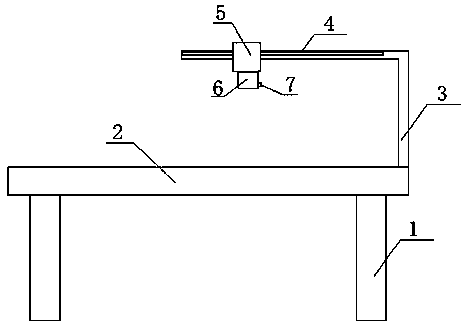
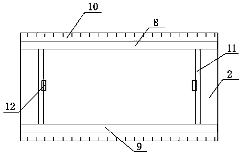
[0012] See figure 1 and figure 2 , a steel plate cutting tool, including a steel plate positioning work platform, an inverted L-shaped support frame 3 arranged on the steel plate positioning work platform, a moving guide rail 4 arranged on the horizontal part of the inverted L-shaped support frame 3, and a moving guide rail 4 The cutting device on the top, the cutting device includes a lifting cylinder 5, an electric cutting machine 6 connected to the lifting cylinder 5, and a network camera 7 arranged on the shell of the electric cutting machine 6, and the steel plate positioning work platform includes a base 1, which is arranged on the base The upper support plate 2, the upper and lower guide rails 8,9 which are arranged on the upper end surface of the support plate 2 and which are oppositely arranged, are arranged on the support plate 2 and are positioned at the sides of the upper and lower guide rails 8,9 and are connected to the upper and lower guide rails 8,9 Parallel ...


PUM


Abstract

The invention discloses a steel plate cutting tool which comprises a steel plate locating working platform, an inverted-L-shaped support frame arranged on the steel plate locating working platform, a moving guide rail arranged at the horizontal part of the inverted-L-shaped support frame, and a cutting device arranged on the moving slide rail, wherein the steel plate locating working platform comprises a base, support plates arranged on the base, and an upper guide rail and a lower guide rail oppositely arranged on the upper end surfaces of the support plates; the two ends of two locating rods are respectively connected on the upper guide rail and the lower guide rail in a sliding manner; clamps are oppositely arranged on the two locating rods; and a lifting cylinder, an electric cutting machine, sliding driving mechanisms of the two locating rods, and a sliding driving mechanism of the cutting device are connected with a controller. According to the steel plate cutting tool, a steel plate is accurately located through adopting the steel plate locating working platform, so that the fixation of the steel plate is guaranteed during the cutting process, and the cutting is guaranteed to be accurate; and besides, the automatic control is carried out through adopting the controller, so that the cutting efficiency is improved.

Description

technical field [0001] The invention relates to the field of steel structure processing, in particular to a steel plate cutting tool. Background technique [0002] The good mechanical properties and low manufacturing cost of steel make it play a pivotal role in the production of the national economy. As a structural material, it supports the country's economic construction, and as a tool material, it is used in all aspects of people's daily life. Most of the existing steel structure materials are assembled and welded by steel plates and rigid beams. The cutting of the existing steel plates is performed by cutting machines for artificial positioning and cutting, which is not accurate and the cutting speed is slow. Contents of the invention [0003] The technical problem to be solved by the present invention is to provide a steel plate cutting tool with accurate cutting and fast cutting speed. [0004] Technical scheme of the present invention is: [0005] A steel plate cu...

Claims


Application Information

Patent Timeline
IPC IPC(8): B23Q3/00B23Q3/18
CPCB23Q3/00B23Q3/18
Inventor 曹雁冰
Owner ANHUI WEIHONG STEEL STRUCTURE GRP
Learn More