Injection mold for rapid mold opening for small plastic gears

A technology for plastic gears and injection molds, applied in the field of injection molds, can solve the problems of affecting the product image of the enterprise, hollowing, and affecting the service life of gears, etc., and achieve the effects of reducing hollowing, simple structure, and speeding up the setting work

Inactive Publication Date: 2016-04-20
重庆和佳机械部件制造有限公司
View PDF0 Cites 0 Cited by
  • Summary
  • Abstract
  • Description
  • Claims
  • Application Information

AI Technical Summary

Problems solved by technology

At present, the commonly used production method of plastic gears is to use injection molds for injection molding. The production speed is fast and the qualified products are very high. However, the current gear injection molds are affected by the ambient temperature during the production of injection molding, and the produced gears sometimes appear hollow in the middle. Phenomenon, which affects the service life of the gear, and affects the image of the company's products

Method used


Image

  • Injection mold for rapid mold opening for small plastic gears
  • Injection mold for rapid mold opening for small plastic gears

Examples


Embodiment 1

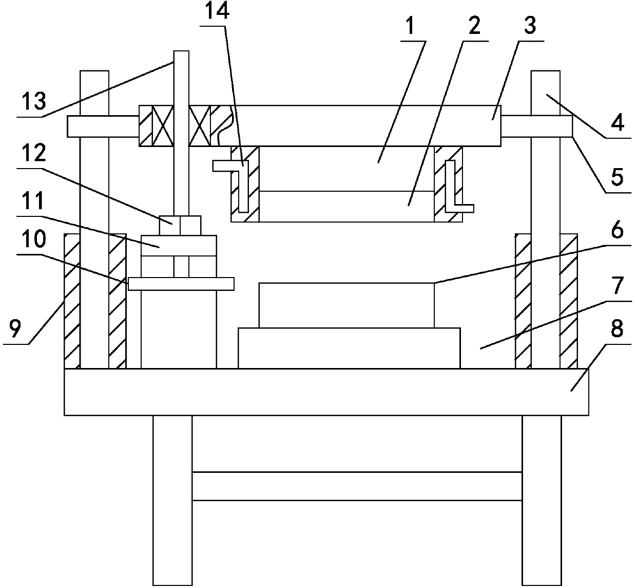
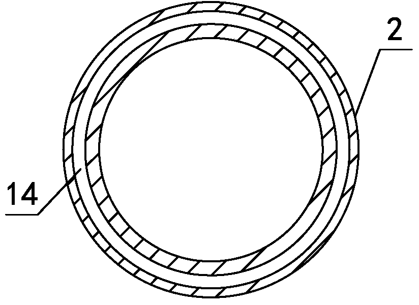
[0015] like figure 1 , figure 2 As shown, the injection mold for quick mold opening of small plastic gears, the injection mold for quick mold opening of small plastic gears, includes a workbench 8, an upper injection mold 1 and an injection lower mold 6 that cooperate with each other, and the lower injection mold 6 is installed on the lower formwork 7, the lower formwork 7 is installed on the workbench 8, the top of the injection molding upper mold 1 is installed on the upper formwork 3, and guide columns 4 are vertically arranged on the workbenches 8 on the left and right sides of the lower formwork 7 respectively. The guide pillars 4 are equipped with guide sleeves 5, which are respectively fixed on the upper template 3, and the outer circumference of the injection molding upper mold 1 is covered with a thermal insulation sleeve 2. For the rubber sleeve 9 for quick mold opening, the height of the top surface of the rubber sleeve 9 is 10mm higher than the height of the top ...

Embodiment 2

[0019] On the basis of Embodiment 1, further changes are made, and the wall thickness of the thermal insulation cover 2 is 55 mm; The thickness becomes 30mm; the distance between the cooling cavity 9 and the side wall of the insulation cover 2 becomes 15mm. Others are the same as embodiment one.

Embodiment 3

[0021] On the basis of embodiment one, further change, the cover wall thickness of described insulation cover 2 is 60mm; The thickness becomes 25mm; the distance between the cooling chamber 9 and the side wall of the insulation cover 2 becomes 20mm. Others are the same as embodiment one.


PUM


Abstract

The invention relates to an injection mold for rapid mold opening for small plastic gears and belongs to the technical field of injection molds. The injection mold comprises a workbench as well as an upper injection mold and a lower injection mold which are matched with each other, wherein the lower injection mold is mounted on a lower mold plate, the lower mold plate is mounted on the workbench, the top of the upper injection mold is mounted on an upper mold plate, guiding columns are vertically arranged on the workbench on left and right sides of the lower mold plate and sleeved with guiding sleeves, the guiding sleeves are correspondingly fixed on the upper mold plate, the periphery of the upper injection mold is sleeved with a heat insulating sleeve made of an aluminium alloy material, the guiding columns are sleeved with rubber sleeves for rapid mold opening, a screw rod is vertically arranged between the heat insulating sleeve and the guiding column on the left side, the upper end of the screw rod is mounted on the upper mold plate in a penetrating manner by the aid of a bearing, the screw rod is sleeved with a nut matched with the screw rod, the nut is fixed on a support, and a cooling cavity is formed in the sleeve wall of the heat insulating sleeve. With the adoption of the injection mold, through design of the cooling cavity, shaping of an injected product can be effectively accelerated.

Description

technical field [0001] The invention relates to an injection mold used for rapid mold opening of small plastic gears, belonging to the technical field of injection molds. Background technique [0002] Gear transmission is a common transmission mode in people's life, and its transmission stability is very high, and its service life is long. With the continuous advancement of science and technology, more and more gears are made of plastic, which are mainly used in an industry with a small transmission torque. The production cost is low, the transportation cost is low, and the safety and maintenance are also convenient. At present, the commonly used production method of plastic gears is to use injection molds for injection molding. The production speed is fast and the qualified products are very high. However, the current gear injection molds are affected by the ambient temperature during the production of injection molding, and the produced gears sometimes appear hollow in the...

Claims


Application Information

Patent Timeline
IPC IPC(8): B29C45/26B29C45/73B29C45/78B29C45/66
Inventor 胡维秀
Owner 重庆和佳机械部件制造有限公司
Why Eureka
Try Eureka