Synchronous belt conveying device of glass substrate

A glass substrate and transmission device technology, applied in the direction of conveyors, transportation and packaging, etc., can solve the problems of shortened service life, rapid wear of the teeth of the toothed synchronous belt 8, and inconvenient replacement of the toothed synchronous belt 8, etc., to achieve Effect of reducing equipment downtime and improving production efficiency

Pending Publication Date: 2016-04-20
ZHENGZHOU XUFEI OPTOELECTRONICS TECH +1
View PDF7 Cites 4 Cited by
  • Summary
  • Abstract
  • Description
  • Claims
  • Application Information

AI Technical Summary

Problems solved by technology

[0004] In the actual operation process, due to the influence of processing, installation and fixing precision, etc., the driving wheel 3 and the driven wheel 6 are not completely aligned in the direction of glass substrate transmission, resulting in the toothed synchronous belt 8 being in contact with the driving wheel 3 and the driven wheel 6. Belt skipping often occurs during the meshing process of the wheel grooves. This unstable transmission method not only aggravates the rapid wear of the teeth of the toothed synchronous belt 8, shortens its service life, and easily causes the glass substrate to shift during the transmission process, which cannot be normal. Going to the next process, causing the lower surface of the glass substrate to be scratched or broken
In addition, since the driving wheels 3 are jointly installed on a driving shaft 2, it is not convenient to replace the toothed synchronous belt 8 with severe wear.

Method used


Image

  • Synchronous belt conveying device of glass substrate
  • Synchronous belt conveying device of glass substrate
  • Synchronous belt conveying device of glass substrate

Examples


Embodiment Construction

[0022] Specific embodiments of the present invention will be described in detail below in conjunction with the accompanying drawings. It should be understood that the specific embodiments described here are only used to illustrate and explain the present invention, and are not intended to limit the present invention.

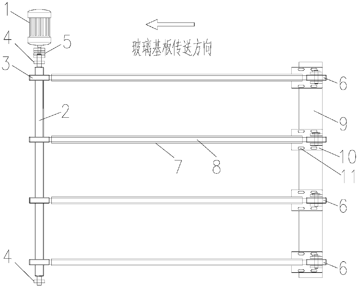
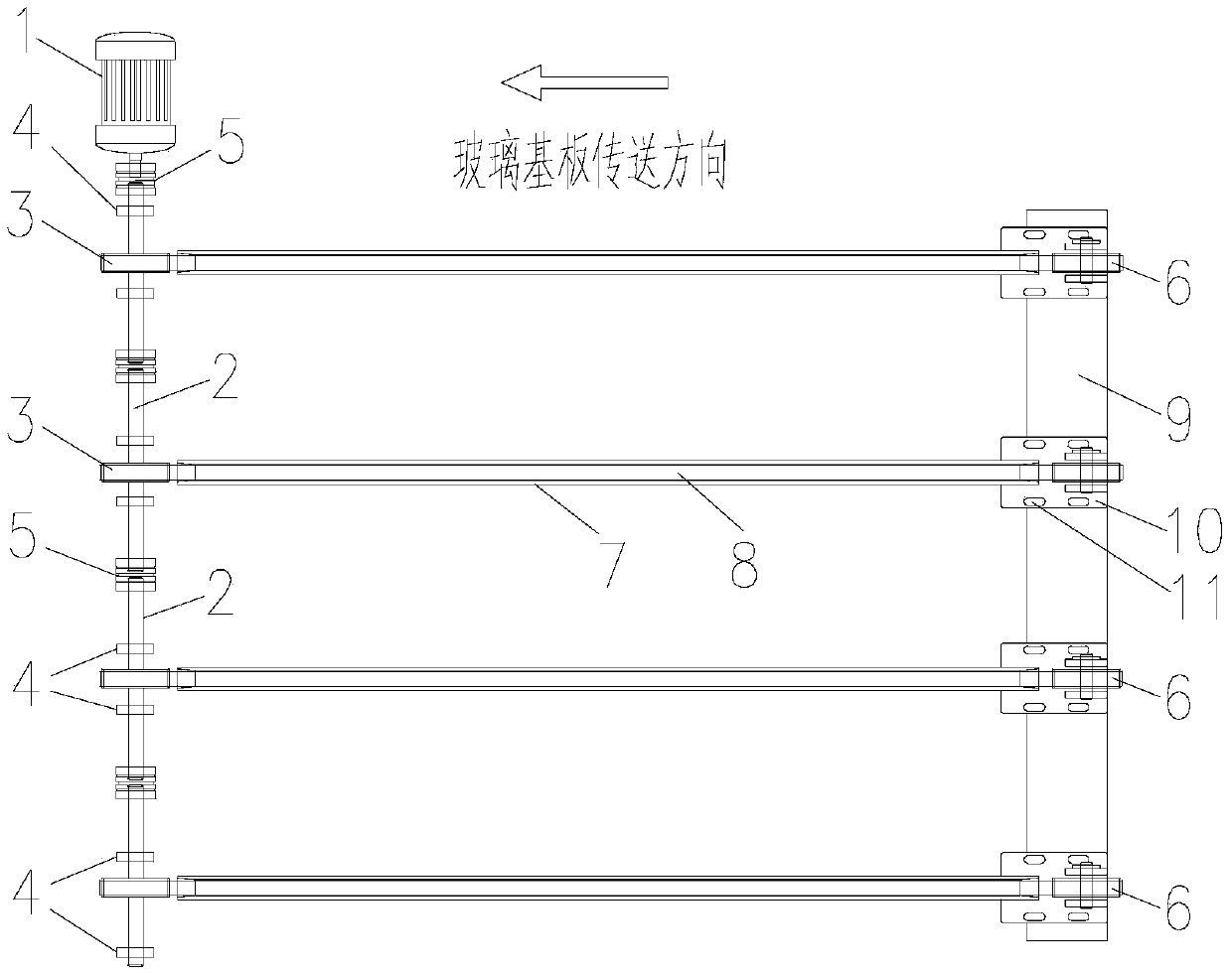
[0023] Such as figure 2 As shown, the present invention provides a synchronous belt transmission device for glass substrates, including a motor 1, a drive shaft driven by the motor 1, a belt seat bearing 4 for supporting the drive shaft, and a drive wheel mounted on the drive shaft 3. The driven wheel 6 installed on the frame 9, and the toothed synchronous belt 8 connecting the driving wheel 3 and the driven wheel 6, the driving shaft includes a plurality of segmented shafts 2 arranged coaxially, adjacent The segmented shafts 2 are connected by couplings 5 ​​, and both ends of each segmented shaft 2 are supported by the bearings with seats 4 .

[0024] Throug...


PUM


Abstract

The invention discloses a synchronous belt conveying device of a glass substrate. The synchronous belt conveying device comprises a motor (1), a driving shaft driven by the motor (1), pillow block bearings (4) for supporting the driving shaft, driving wheels (3) mounted on the driving shaft, driven wheels (6) mounted on a rack (9), and tooth-shaped synchronous belts (8) for connecting the driving wheels (3) with the driven wheels (6), wherein the driving shaft comprises a plurality of subsection shafts (2) which are arranged coaxially and the adjacent subsection shafts (2) are connected through shaft couplers (5); the two ends of each subsection shaft (2) are supported through the corresponding pillow block bearing (4). The driving shaft comprises the plurality of subsection shafts and the subsection shafts are connected through the shaft couplers; transverse adjustment of the driving wheels can be conveniently realized through adjusting the length of the shaft couplers, so that tooth grooves of the driving wheels and the driven wheels are on the same straight line, and furthermore, bad engagement of the tooth-shaped synchronous belts and the tooth grooves is effectively reduced, and abrasion and belt skipping problems of the tooth-shaped synchronous belts are reduced. Furthermore, when the tooth-shaped synchronous belts are abraded for a long period and need to be replaced, the tooth-shaped synchronous belts can be independently replaced, so that the stopping time of the device is shortened and the production efficiency is improved.

Description

technical field [0001] The invention relates to a conveying device for a glass substrate, in particular to a synchronous belt conveying device for a glass substrate. Background technique [0002] The glass substrate needs to be conveyed by the conveying device during the size processing. The transmission device in the existing size processing process is driven by a motor to rotate a driving shaft, and a driving shaft drives 3-5 synchronous belts (generally toothed toothed belts) to rotate, and the glass substrate is carried on the synchronous belt to complete Transfer work between workstations. [0003] Such as figure 1 As shown, the existing synchronous belt transmission device includes a motor 1, a driving shaft 2, a driving wheel 3, a seat bearing 4, a shaft coupling 5, a driven wheel 6, a flat supporting plate 7 and a toothed synchronous belt 8. The motor 1 drives the drive shaft 2 to rotate through the coupling 5, the main transmission shaft 2 is rotatably supported ...

Claims


Application Information

Patent Timeline
Patent Type & Authority Applications(China)
IPC IPC(8): B65G15/20B65G23/24
CPCB65G15/20B65G23/24B65G2201/022
Inventor 张佳磊
Owner ZHENGZHOU XUFEI OPTOELECTRONICS TECH
Why Eureka
Try Eureka