


Quick Research
Generate reliable direction feasibility study reports for your R&D in just a few steps.

Technical Q&A
Discover and master advanced knowledge NOW. Basics, ideas, possibilities, all at once.

Find Solutions
As an expert in R&D theories, this can generate solutions to your technical problems instantly.

Evaluate Feasibility
Analyze your overall solution with one click, know your potential R&D risks in advance.

Monitor Landscape
Get weekly tech updates, stay abreast of the latest tech innovations and key insights.
Cone discharge device and method for realizing orderly discharge of cone materials
A cone, feeding technology, applied in the direction of conveyor objects, transportation and packaging, loading/unloading, etc., can solve the problems of long sorting time of cone parts, prone to mechanical failure, large volume of the vibrating plate, etc., to achieve simple structure, Reduce the processing cost and energy consumption, and the effect of uniform discharge
- Summary
- Abstract
- Description
- Claims
- Application Information
AI Technical Summary
Problems solved by technology
Method used
Image

Examples
Embodiment 1
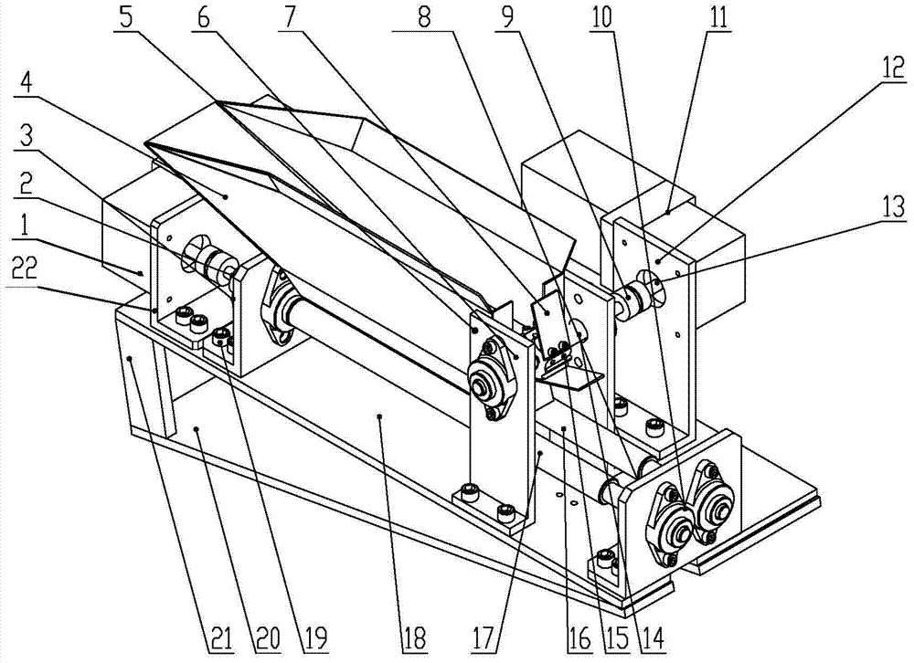
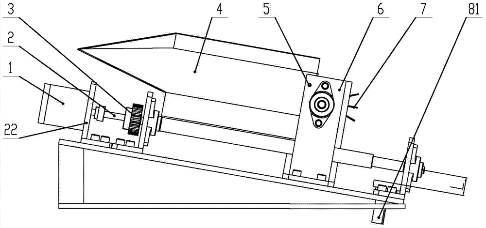
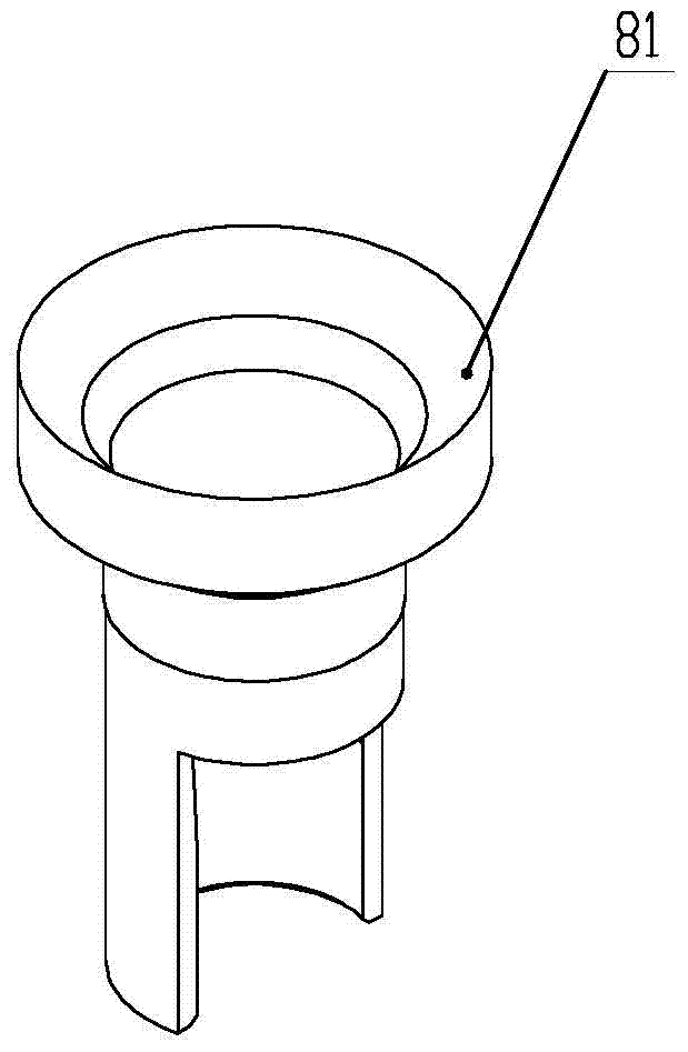
[0041] A cone discharge device such as figure 1 , figure 2 , Figure 3-1 , Figure 3-2 , Image 6 , Figure 7 As shown, the cone discharge device includes a horizontal base 20, a base plate 18 installed on the horizontal base 20 by a base plate mount 21, a casing 4 for adorning the cone to be discharged, a dial for transferring the cone Sheet 7, roller I16, roller II17, drive roller I, motor I1 of roller II, drive the motor II11 of the plectrum and the falling hopper I81 for connecting the cone material;
[0042] The box body 4 is installed on the bottom plate 18 through the box body support seat 6;
[0043] The motor I1 and the motor II11 are installed on both ends of the bottom plate 18 through the motor mounting base I22 and the motor mounting base II12 respectively;
[0044] The roller II17 is connected with the rotating shaft of the motor I1 through the circlip 2, the roller I16 is connected with the roller II17 through the gear 3 meshing, and the two axes are parall...
Embodiment 2
[0049] A cone discharge device such as figure 1 , Figure 4 , Figure 5-1 , Figure 5-2 , Image 6 , Figure 7 As shown, the basic structure of the cone discharge device is the same as that of Embodiment 1, and the cone discharge device also includes a horizontal base 20, a bottom plate 18 installed on the horizontal base 20 through a bottom plate mounting seat 21, and is used for holding The box body 4 for arranging the cones, the paddle 7 for conveying the cones, the roller I16, the roller II17, the motor I1 driving the roller I, the roller II, and the motor II11 driving the paddle are different from the first embodiment The difference is that the structure of the falling hopper II 82 for connecting the cone material is slightly different from that of the falling hopper I 81, but its overall structure is similar; the falling hopper II 82 for connecting the cone material is also made of two different diameter It is an integral structure composed of segmented cylinders. T...
Embodiment 3
[0052] A method for feeding cones in an orderly manner, the method is to use the cone discharge device described in Embodiment 1 to realize the method for orderly discharging cone materials, that is: the materials that enter the device randomly After the conical parts of the box go through the feeding step and the unloading step, the conical parts are sent out in order with the small end facing up:
[0053] A. Feeding steps—feeding method with the big end facing up: motor Ⅱ11 drives roller Ⅱ17 to rotate counterclockwise, roller Ⅱ17 drives roller Ⅰ16 to rotate clockwise through gear 3, and the cone parts falling from box 4 are received by roller Ⅰ16 1. The friction force of the roller II17 moves upwards, and finally the big end faces upwards, and the small end falls between the two shafts and slides down along the direction of the roller; the motor II11 drives the ratchet 15 to rotate, and the paddle 7 on the ratchet rotates the roller Ⅰ16. The unadjusted cone parts on the roll...
PUM
 Abstract
Description
Claims
Application Information
 - R&D Engineer
- R&D Manager
- IP Professional
- Industry Leading Data Capabilities
- Powerful AI technology
- Patent DNA Extraction
Browse by: Latest US Patents, China's latest patents, Technical Efficacy Thesaurus, Application Domain, Technology Topic, Popular Technical Reports.
© 2024 PatSnap. All rights reserved.Legal|Privacy policy|Modern Slavery Act Transparency Statement|Sitemap|About US| Contact US: help@patsnap.com