
A material transfer device

A technology for transferring devices and materials, which is applied to conveyor objects, transportation and packaging, conveyors, etc., can solve the problems of inability to send steel pipes into the straightening machine for straightening, dangers caused by traveling and hoisting, and safety of steel pipes. The effect of improving space utilization, avoiding cranes, and improving work efficiency

Active Publication Date: 2017-11-24
HUZHOU RENXIN BEARING STEEL PIPE
View PDF1 Cites 0 Cited by
  • Summary
  • Abstract
  • Description
  • Claims
  • Application Information

AI Technical Summary

Problems solved by technology

[0002] In the traditional steel pipe production, after the spheroidized annealed material is released from the furnace, the material needs to be transported to the area to be straightened by the crane, and then used to transfer the material from the area to be straightened to the straightening rack during straightening production. , Repeated transportation of materials wastes manpower and needs to be manually loaded sequentially. The labor intensity is high, and a large number of cranes are used to lift steel pipes, which has potential safety hazards. Driving cranes are prone to danger, and the lifting speed is slow, requiring many hook workers and driving drivers. Human cooperation, low efficiency
For example, CN104174780A discloses a steel pipe straightening machine feeding device, which provides a device to solve the problem of steel pipe straightening machine feeding, but it still cannot directly send the steel pipe after heat treatment to the straightening machine for straightening.

Method used


Image

  • A material transfer device
  • A material transfer device
  • A material transfer device

Examples


Embodiment 1

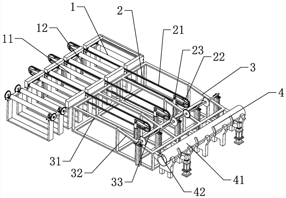
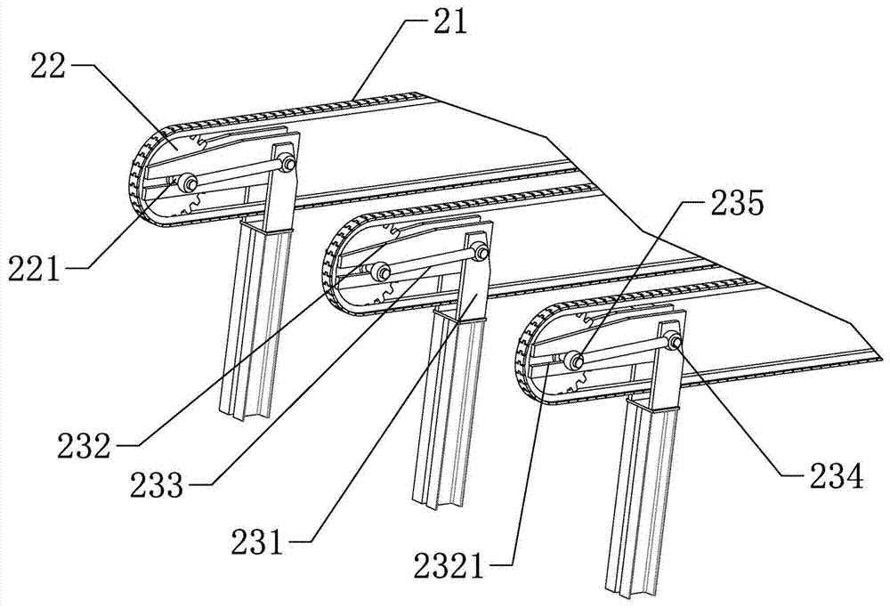
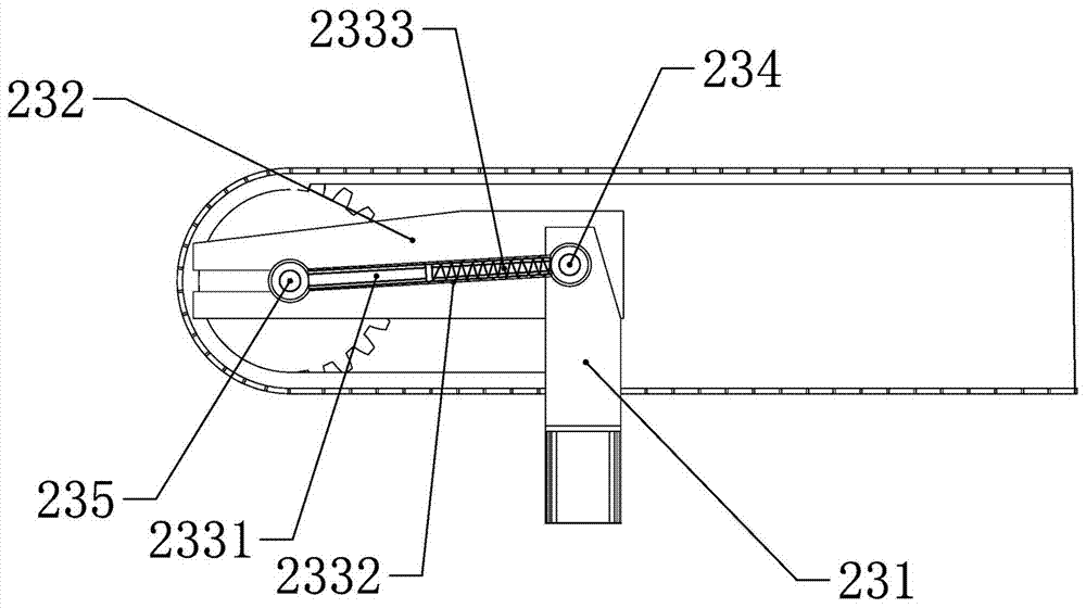
[0028] according to Figure 1 ~ Figure 4 As shown, a material transfer device includes: a straight material rack 1, a translation mechanism 2, a horizontal material rack 3 and a feeding table 4; the straight material rack 1 and the feeding table 4 are located on both sides of the horizontal material rack 3, and the The mechanism 2 runs through the straight material rack 1 and one end extends into the horizontal material rack 3; the straight material rack 1 is used to remove the steel pipe from the annealing furnace, and the translation mechanism 2 is used to translate the steel pipe on the straight material rack 1 to the horizontal material rack 3, the horizontal material rack 3 is used to send the steel pipes into the feeding table 4 in turn.

[0029] according to figure 1 As shown, the straight material rack 1 includes a number of parallel conveying rollers 11 for conveying materials, and a steel frame 12 for supporting the conveying rollers 11; the translation mechanism 2 ...

Embodiment 2

[0035] The difference from the above-mentioned embodiment 1 is that there are two sets of conveying rollers 11, and the straight material frame 1 includes 2 to 6 sets of conveying rollers 11, and the conveying rollers 11 can be freely increased or decreased according to the length of the steel pipe through the grouped conveying rollers 11. group, to realize the function of adjusting the length of the straight material rack 1, and save the working space.


PUM


Abstract

The invention relates to the field of steel pipe processing and manufacturing, in particular to a material transfer device, comprising: a row material rack, a translation mechanism, a horizontal material rack and a feeding platform; the straight material rack and the feeding platform are respectively located on both sides of the horizontal material rack , the translation mechanism traverses through the straight material rack and one end extends into the horizontal material rack; the straight material rack is used to remove the steel pipe from the annealing furnace, and the translation mechanism is used to translate the steel pipe on the straight material rack to the horizontal On the material rack, the horizontal material rack is used to sequentially send the steel pipes to the feeding table; a material transfer device described in the present invention avoids driving and hoisting, and adopts a multi-directional transmission mode throughout the entire process, which improves the transmission speed and increases Improve production efficiency, reduce operators and improve safety performance.

Description

technical field [0001] The invention relates to the field of steel pipe processing and manufacturing, in particular to a material transfer device. Background technique [0002] In the traditional steel pipe production, after the spheroidized annealed material is released from the furnace, the material needs to be transported to the area to be straightened by the crane, and then used to transfer the material from the area to be straightened to the straightening rack during straightening production. , Repeated transportation of materials wastes manpower and needs to be manually loaded sequentially. The labor intensity is high, and a large number of cranes are used to lift steel pipes, which has potential safety hazards. Driving cranes are prone to danger, and the lifting speed is slow, requiring many hook workers and driving drivers. People cooperate, and the efficiency is low. For example, a steel pipe straightening machine feeding device disclosed in CN104174780A provides a...

Claims


Application Information

Patent Timeline
Patent Type & Authority Patents(China)
IPC IPC(8): B65G47/34
CPCB65G47/34B65G2201/0276
Inventor 曹晓明胡海云夏金孝李杰
Owner HUZHOU RENXIN BEARING STEEL PIPE
Learn More