
Axial turbomachine compressor outer casing with seal

An axial-flow turbine and external casing technology, which is applied in the fields of controlling the axial-flow turbine sealing device, the axial-flow turbine compressor external casing, and the axial-flow turbine external casing, can solve the problem of limited quantity and limited efficiency gain. and other problems, to achieve the effect of large position accuracy and accurate adjustment

Inactive Publication Date: 2016-04-20
SAFRAN AERO BOOSTERS SA
View PDF6 Cites 3 Cited by
  • Summary
  • Abstract
  • Description
  • Claims
  • Application Information

AI Technical Summary

Problems solved by technology

However, the gains in efficiency offered by such devices are limited, as are the number of configurations to which they can be accommodated

Method used


Image

  • Axial turbomachine compressor outer casing with seal
  • Axial turbomachine compressor outer casing with seal
  • Axial turbomachine compressor outer casing with seal

Examples


Embodiment Construction

[0045] In the following description, the terms internal or internal and external or external refer to the position relative to the axis of rotation of the axial turbine.

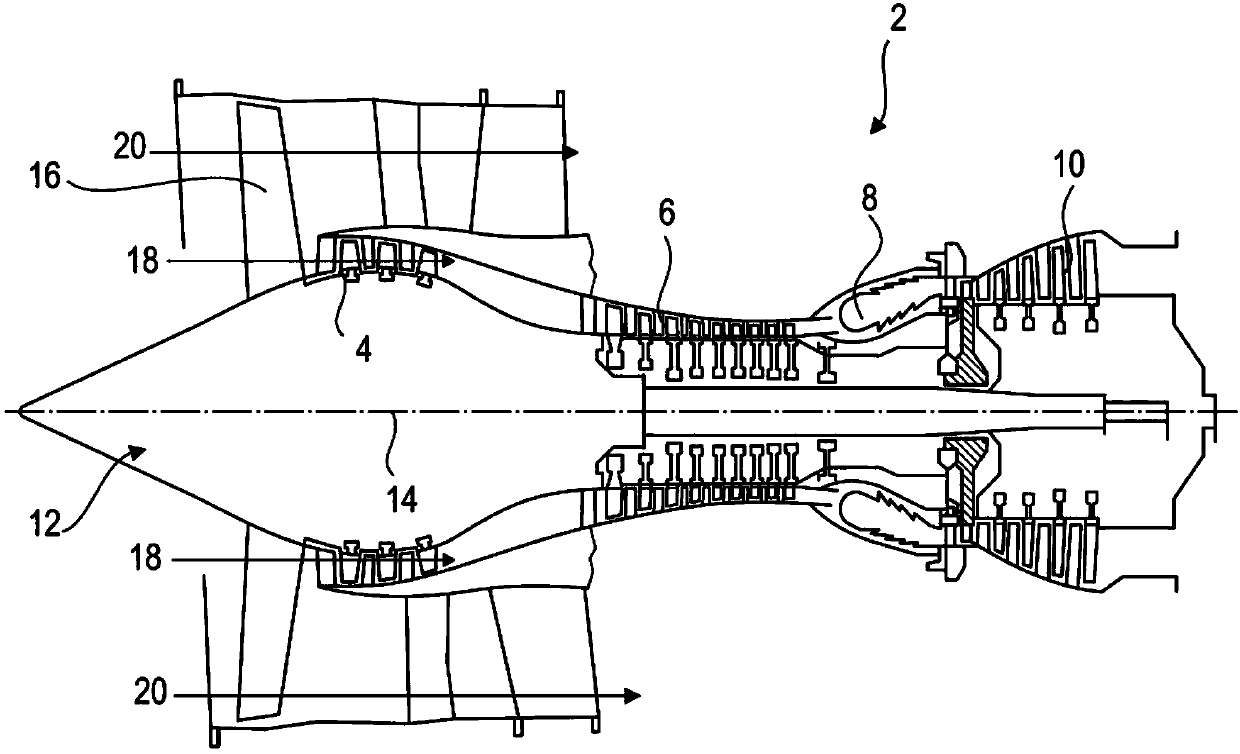
[0046] figure 1 It is a simplified description of the axial turbine. In this particular example, it is a bypass turbojet engine. The turbojet engine 2 includes a first compression level called a low-pressure compressor 4, a second compression level called a high-pressure compressor 6, a combustion chamber 8, and one or more turbine levels 10. In operation, the mechanical power of the turbine 10 transmitted to the rotor 12 via the central shaft turns the two compressors 4 and 6. The compressor includes rows of rotor blades associated with rows of stator blades. Therefore, the rotation of the rotor about its axis of rotation 14 generates a flow of air and gradually compresses this flow until it enters the combustion chamber 8.

[0047] An inlet blower commonly referred to as a fan 16 is coupled to the rotor 12 a...


PUM


Abstract

The invention relates to an axial turbomachine compressor outer casing (28). The casing (28) comprises a sealing device (34) collaborating with a row of rotor blades (24). The casing (28) comprises a wall (30) with an annular groove (38) in which the sealing device (34) is housed. The sealing device (34) comprises a segmented outer shroud (36) and a plurality of piezoelectric actuators (46) moving the shroud (36) radially in the groove (38) so as to open or close the functional clearance. The invention also proposes a method for controlling the sealing device (34) for a turbojet engine, and the method comprises a step of measuring the altitude and a step of adjusting a clearance according to the altitude.

Description

Technical field [0001] The invention relates to an outer casing of an axial turbine with a sealing device. More specifically, the present invention relates to an axial turbine compressor outer casing equipped with a sealing device surrounding a row of rotor blades. The invention also relates to an axial turbine. The invention also relates to a method for controlling the sealing device of an axial turbine. Background technique [0002] In order to improve efficiency, the turbine is provided with a sealing device surrounding its blade row. These devices allow changing the gap between the inner surface of the casing and the outer ends of the rotor blades arranged inside the inner casing. Therefore, under operating conditions, the gap can be reduced in order to limit dynamic leakage between the surface and the blade. [0003] For an outer shield connected to an outer casing through a deformable element, such a device may include the outer casing as a support. In case of changing f...

Claims


Application Information

Patent Timeline
IPC IPC(8): F01D11/20
CPCF05D2260/407F01D11/22F04D27/0246F04D29/164F04D29/526Y02T50/60F01D1/20F01D11/025F01D25/24
Inventor J-F.科特奎斯P.迈诺特
Owner SAFRAN AERO BOOSTERS SA
Learn More