Efficient hot air engine

A hot gas engine and high-efficiency technology, which is applied in hot gas variable displacement engine devices, closed gas positive displacement engine factories, mechanical equipment, etc., can solve problems such as unreasonable structural design, restricted efficiency of heat engines, and inability to be popularized and used.

Active Publication Date: 2016-04-20
胥荣欣
View PDF4 Cites 2 Cited by
  • Summary
  • Abstract
  • Description
  • Claims
  • Application Information

AI Technical Summary

Problems solved by technology

[0002] A traditional heat engine is generally composed of a moving cylinder body and heaters and coolers arranged at both ends of the moving cylinder body. A moving piston is arranged in the moving cylinder body to divide the moving cylinder body into a heating cavity and a cooling cavity. The two cavities However, due to the unreasonable structural design of the existing heat generator, part of the heat energy enters the cooling end through the regenerator while heating and expanding to push the power piston to do work, and the heat energy is neutralized, resulting in hot gas The efficiency of the machine is restricted, so it cannot be popularized and used

Method used


Image

  • Efficient hot air engine

Examples


Embodiment Construction

[0015] The high-efficiency air heater of the present invention will be described in further detail below in conjunction with the accompanying drawings and specific embodiments.

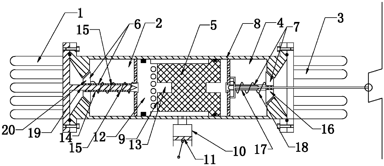
[0016] As shown in the figure, the high-efficiency heat engine of the present invention includes an expansion cavity 2 with a heater 1 and a compression cavity 4 with a cooler 3. The two cavities are connected through a regenerator 5, and the heater 1 No. 1 valve device 6 is provided in the passage between the expansion chamber 2 and the No. 2 valve device 7 is provided in the passage between the cooler 3 and the compression chamber 4. The No. 1 valve device 6 can close or open the heater and the expansion chamber The channel between the bodies, the second valve device 7 can close or open the channel between the cooler 3 and the compression cavity 4 .

[0017] Wherein, in the present embodiment, said expansion cavity 2 and compression cavity 4 are located in a gas-shifting cylinder body 8, and a gas-m...


PUM


Abstract

The invention discloses an efficient hot air engine. The efficient hot air engine comprises an expansion cavity with a heater and a compression cavity with a cooler. The two cavities are connected and communicated through a heat regenerator. A first valve device is arranged on a channel between the heater and the expansion cavity. A second valve device is arranged on a channel between the cooler and the compression cavity. The first valve device can close or open the channel between the heater and the expansion cavity. The second valve device can close or open the channel between the cooler and the compression cavity. After the structure is adopted, during heating expansion at the heating end, the cooling end is closed; otherwise, during cooling condensation at the cooling end, the other heating end is closed, heating energy is sufficiently utilized, and therefore the efficiency of the hot air engine is improved.

Description

technical field [0001] The invention relates to an improvement of a Stirling engine, in particular to a high-efficiency heat engine. Background technique [0002] A traditional heat engine is generally composed of a moving cylinder body and heaters and coolers arranged at both ends of the moving cylinder body. A moving piston is arranged in the moving cylinder body to divide the moving cylinder body into a heating cavity and a cooling cavity. The two cavities However, due to the unreasonable structural design of the existing heat generator, part of the heat energy enters the cooling end through the regenerator while heating and expanding to push the power piston to do work, and the heat energy is neutralized, resulting in hot gas The efficiency of the machine is restricted, so that it cannot be popularized and used. Contents of the invention [0003] The technical problem to be solved by the present invention is to provide a high-efficiency heat engine that can make full ...

Claims


Application Information

Patent Timeline
Patent Type & Authority Applications(China)
IPC IPC(8): F02G1/044F02G1/057
CPCF02G1/044F02G1/057F02G1/043F02G1/05F02G2242/10F02G2270/30F02G2253/04F02G2270/90F02G2243/30F02G2243/34F02G1/055
Inventor 夏致俊
Owner 胥荣欣
Why Eureka
Try Eureka