
Bevel gear orthogonal transmission mechanism

A transmission mechanism, bevel gear technology, applied in the direction of gear transmission, transmission, transmission parts, etc., can solve the problem of large occupied space and so on

Inactive Publication Date: 2016-04-20
JIANGSU ZHONGNENG POWER EQUIP
View PDF8 Cites 1 Cited by
  • Summary
  • Abstract
  • Description
  • Claims
  • Application Information

AI Technical Summary

Problems solved by technology

This type of structure must have a solid steel foundation, and it takes up a lot of space. Large-scale equipment must be used during machining to meet the technical requirements.

Method used


Image

  • Bevel gear orthogonal transmission mechanism
  • Bevel gear orthogonal transmission mechanism

Examples


Embodiment Construction

[0017] The following will clearly and completely describe the technical solutions in the embodiments of the present invention with reference to the drawings in the embodiments of the present invention.

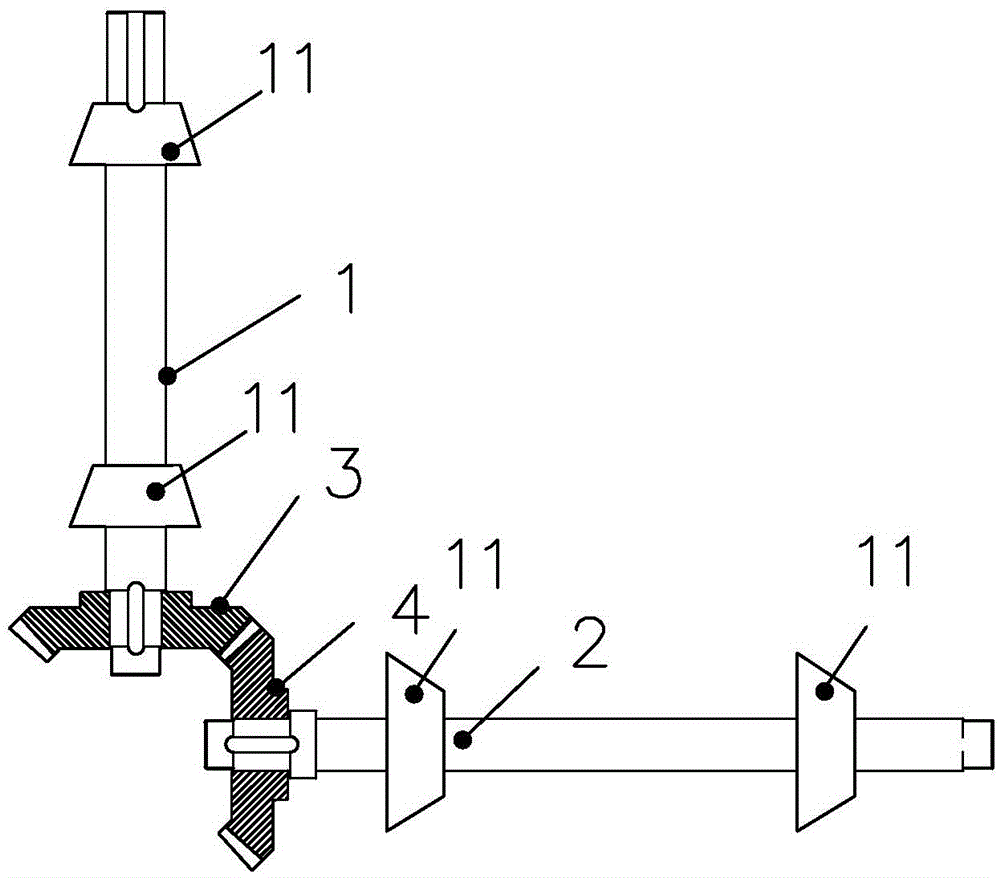
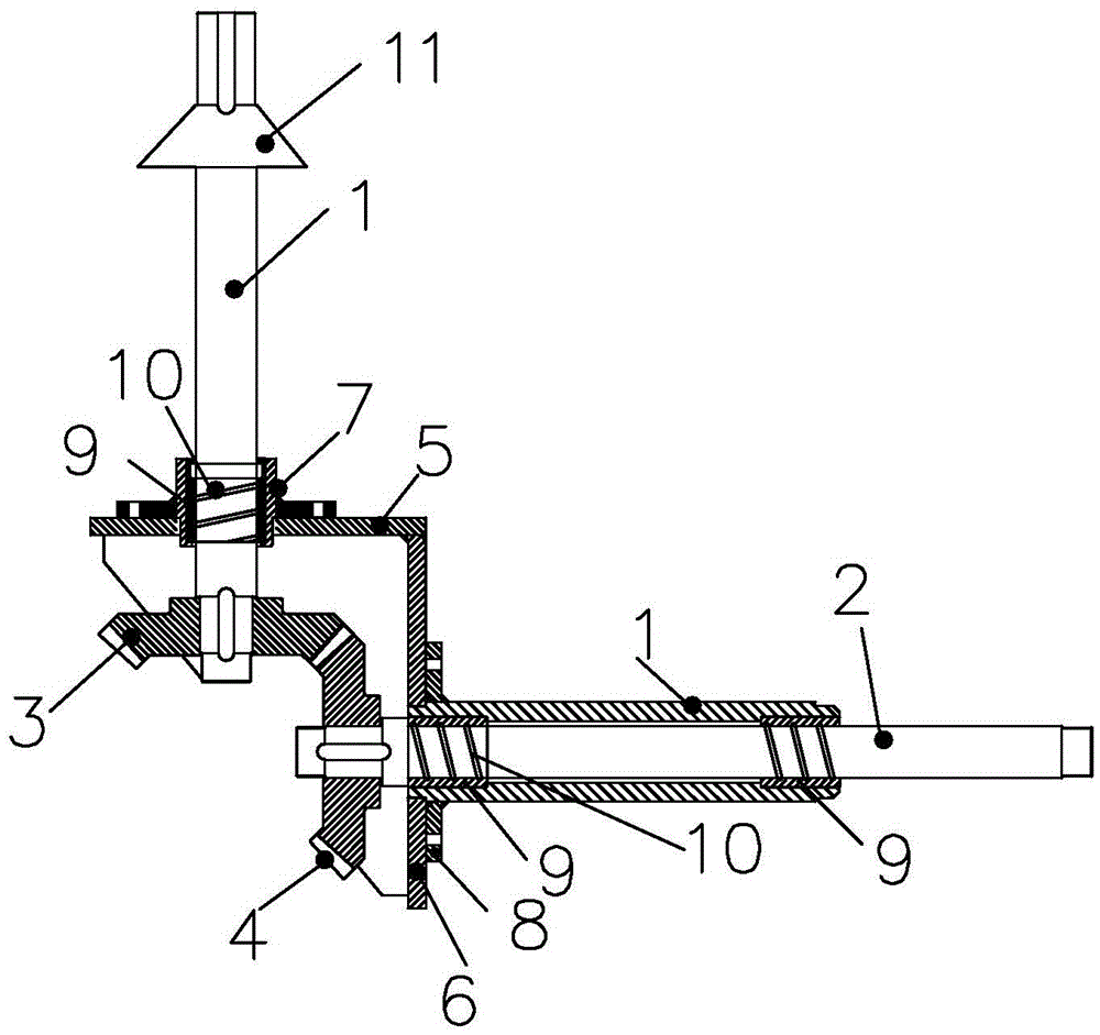
[0018] figure 1 As shown, a bevel gear orthogonal transmission mechanism proposed in this embodiment is generally used in a specific cylinder space, including a driving bevel gear 3 and a driven bevel gear 4, and the driving bevel gear 3 is connected to A driving shaft 1, the driven bevel gear 4 is connected to a driven shaft 2, the ends of the driving shaft 1 and the driven shaft 2 are provided with support bearings 11, and the mechanism also includes a square support seat, the support seat It has a horizontal end 5 and a vertical end 6; the driving shaft 1 passes through the horizontal end 5 of the support base and connects the driving bevel gear 3; the driven shaft 2 passes through the vertical end of the support base. The straight end 6 is connected to the driven bevel ge...


PUM


Abstract

The invention discloses a bevel gear orthogonal transmission mechanism, comprising a driving bevel gear and a driven bevel gear, wherein the driving bevel gear is connected with a driving shaft, and the driven bevel gear is connected with a driven shaft; the transmission mechanism also comprises an angle rule type support seat, wherein the support seat is provided with a horizontal end and a vertical end; the driving shaft passes through the horizontal end of the support seat and then is connected with the driving bevel gear; the driven shaft passes through the vertical end of the support seat and then is connected with the driven bevel gear. The invention provides the novel bevel gear orthogonal transmission mechanism with the advantages of ensuring the axes of the driving shaft and the driven shaft to be perpendicularly intersected, being simple in structure, trouble-saving in machining, and smaller in size, and thus indirectly lowering production cost.

Description

technical field [0001] The invention relates to a bevel gear orthogonal transmission mechanism. Background technique [0002] figure 1 A bevel gear orthogonal transmission mechanism is provided for the prior art. The bevel gear is used for transmission between intersecting shafts and can change the transmission direction. In the existing bevel gear orthogonal transmission, the two shafts of the bevel gear The axes must be perpendicular to each other and intersect. In addition, the holes for the two support bearings on the gear shaft must be concentric. This kind of structural form must have a solid steel foundation, and it takes up a relatively large space. Large-scale equipment must be used during machining to meet the technical requirements. Contents of the invention [0003] Aiming at the existing technical problems, the present invention provides a new bevel gear orthogonal transmission mechanism, which not only ensures that the axes of the driving shaft and the dri...

Claims


Application Information

Patent Timeline
IPC IPC(8): F16H1/14F16H57/023
CPCF16H1/14F16H57/023
Inventor 丁为平陈克祥陈太文
Owner JIANGSU ZHONGNENG POWER EQUIP
Learn More