
Lens used for lighting device with arc-shaped lampshade and lighting device

A lighting device and lens technology, which is applied to the components of lighting devices, lighting devices, fixed lighting devices, etc., can solve the problems of affecting lighting quality, large diameter of light source board and lens, high cost of LED lamp beads, light source board and lens , to achieve uniform brightness distribution, improve lighting quality, and reduce production costs

Inactive Publication Date: 2016-04-20
FOSHAN ELECTRICAL & LIGHTING
View PDF5 Cites 3 Cited by
  • Summary
  • Abstract
  • Description
  • Claims
  • Application Information

AI Technical Summary

Problems solved by technology

[0002] The existing lighting devices with arc-shaped lampshades on the market include ceiling lamps. The light emitted by the lamp beads of the ceiling lamps is emitted through the arc-shaped lampshade, but the brightness of the arc-shaped lampshade will be uneven due to the insufficient light emitting angle of the lamp beads. In order to solve this problem, a lighting device with a lens appears on the market, through which the light generated by the LED lamp beads is diffused
[0003] Although the uniformity of light emission of the lighting device can be improved through the lens, in order to achieve this purpose, the LED lamp bead must be arranged near the edge of the arc-shaped lampshade. Correspondingly, the diameter of the light source board and the lens must be larger, resulting in the , the cost of the light source board and the lens is relatively high, so it is necessary to design a lens that can achieve uniform light emission and save the manufacturing cost of the lighting device and the lighting device using the lens

Method used


Image

  • Lens used for lighting device with arc-shaped lampshade and lighting device
  • Lens used for lighting device with arc-shaped lampshade and lighting device
  • Lens used for lighting device with arc-shaped lampshade and lighting device

Examples


Embodiment Construction

[0021] In order to make the object, technical solution and advantages of the present invention clearer, the present invention will be further described in detail below in conjunction with the accompanying drawings. It is only stated here that the words for directions such as up, down, left, right, front, back, inside, and outside that appear or will appear in the text of the present invention are only based on the accompanying drawings of the present invention, and are not specific to the present invention. limited.

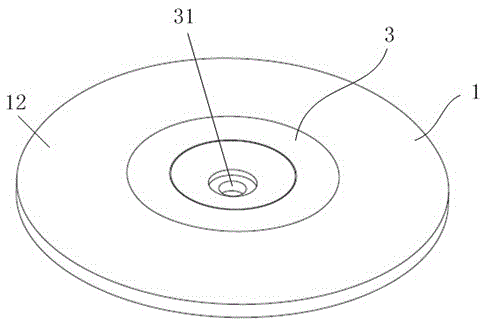
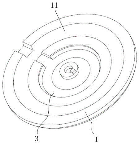
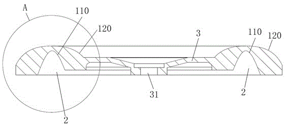
[0022] See attached figure 1 to attach Figure 5 , the invention discloses a lens used for lighting devices of arc-shaped lampshades. The lens is applied to a ceiling lamp and includes a ring-shaped lens body 1. The bottom surface of the lens body 1 is provided with an annular groove 2 for accommodating lamp beads. , the inner wall of the annular groove 2 is a first refraction surface 11, the upper surface of the lens body 1 is provided with an annular raised s...


PUM


Abstract

The invention discloses a lens used for a lighting device with an arc-shaped lampshade. The lens comprises an annular lens body. Annular grooves for containing lamp beads are formed in the bottom face of the lens body. The inner walls of the annular grooves serve as first refraction surfaces. An annular convex second refraction surface is arranged on the upper surface of the lens body. Light emitted by the lamp beads sequentially passes through the first refraction surfaces and the second refraction surface and then is emitted out. The outer circle diameter of the lens body is smaller than or equal to 80 mm, and the beam angle of the lens body ranges from 150 degrees to 175 degrees. The invention further discloses the lighting device. The lens is applied to the lighting device with the arc-shaped lampshade. During application, the lamp beads are arranged in the annular grooves, the light emitted by the lamp beads is refracted through the first refraction surfaces and the second refraction surface of the lens body and then diffused, the diffusion angle of the light is increased, the outer circle diameter and the beam angle of the lens body are controlled, and it can be guaranteed that the brightness of the arc-shaped lampshade is evenly distributed on the basis that the production cost of the lighting device is reduced.

Description

technical field [0001] The invention relates to the field of lenses, in particular to a lens used for an illumination device of an arc lampshade and an illumination device using the lens. Background technique [0002] The existing lighting devices with arc-shaped lampshades on the market include ceiling lamps. The light emitted by the lamp beads of the ceiling lamps is emitted through the arc-shaped lampshade, but the brightness of the arc-shaped lampshade will be uneven due to the insufficient light emitting angle of the lamp beads. In order to solve this problem, a lighting device with a lens appears on the market, and the light generated by the LED lamp beads is diffused through the lens. [0003] Although the uniformity of light emission of the lighting device can be improved through the lens, in order to achieve this purpose, the LED lamp bead must be arranged near the edge of the arc-shaped lampshade. Correspondingly, the diameter of the light source board and the lens...

Claims


Application Information

Patent Timeline
Patent Type & Authority Applications(China)
IPC IPC(8): F21S8/04F21V3/00F21V5/04F21V19/00F21Y115/10
CPCF21S8/04F21V3/00F21V5/04F21V19/001
Inventor 魏彬朱奕光梁银金王善越黄有灿
Owner FOSHAN ELECTRICAL & LIGHTING
Learn More