Imaging method and imaging apparatus for visual inspection of lower surface of sheet material

A technology of visual inspection and imaging method, which is applied in the direction of measuring device, material analysis, material analysis through optical means, etc. It can solve problems such as inability to accurately reflect the passing state of the strip, insertion into the inner side of the roller table, and malfunction of the flap. Achieve the effect of avoiding blind spots in visual inspection, avoiding unsafe factors, and ensuring safe passage

Active Publication Date: 2016-04-20
BAOSHAN IRON & STEEL CO LTD
View PDF8 Cites 2 Cited by
  • Summary
  • Abstract
  • Description
  • Claims
  • Application Information

AI Technical Summary

Problems solved by technology

Since HMD (HotMetalDetector, hot metal detector) is generally used on site to detect steel passing signals, and HMD is affected by external factors such as water vapor, the output signal cannot accurately reflect the passing state of strip steel, which may lead to misoperation of the guide flap , the strip head may be directly inserted into the inner side of the roller table due to the existence of the buckle head, which will cause great harm to the production
In addition, the turning of the guide flap is generally carried out by pneumatic or hydraulic means, and the system runs continuously for a long time, and there are also unstable factors
In addition, in the visual inspection of the lower surface, the detection cannot be carried out because the head of the strip needs to pass through, so that there is a detection blind spot in the detection system
[0003] Chinese patent 200620048985.6 discloses a guide flap device on a roller conveyor line, which discloses a guide flap device on a roller conveyor line, It solves the technical problem of avoiding space when material detection or other operations are required on the continuous material conveying line, but it does not involve the technology of surface visual detection of hot-rolled strip steel and medium-heavy plates using fixed guide plates

Method used


Image

  • Imaging method and imaging apparatus for visual inspection of lower surface of sheet material
  • Imaging method and imaging apparatus for visual inspection of lower surface of sheet material
  • Imaging method and imaging apparatus for visual inspection of lower surface of sheet material

Examples


Embodiment Construction

[0020] The present invention will be further described below in conjunction with the accompanying drawings and specific embodiments.

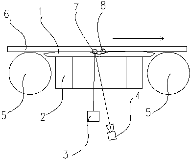
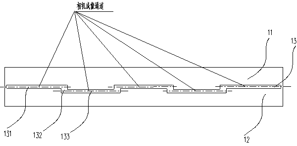
[0021] see Figure 1 to Figure 3 , an imaging method for visual inspection of the lower surface of a plate, aligning several cameras 4 and several lighting sources 3 with a through-slot 13 opened on the guide plate 1 for imaging, and the through-slot 13 is arranged in a staggered manner and runs through , the camera 4 and the lighting source 3 are located below the guide plate channel 13, and the guide plate 1 is fixedly installed between two rollers 5 of the roller table. The through groove 13 becomes a camera imaging channel, and the camera 4 performs imaging detection on the lower surface of the plate 6 passing through the through groove 13 of the guide plate.

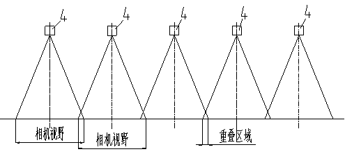
[0022] The camera 4 and the illumination light source 3 are combined and paired to form an image, and the imaging field of view covers each section of the channel in the through gro...


PUM


Abstract

The invention relates to machine vision surface detection technology, especially to an imaging method and imaging apparatus for visual inspection of the lower surface of a sheet material. The imaging method for visual inspection of the lower surface of the sheet material comprises the following steps: aligning a plurality of cameras (4) and a plurality of illumination light sources (3) with a through groove (13) arranged on a guide plate (1) for imaging, wherein the number of imaging positions (7 and 8) is two, the through groove is arranged in a stagger and through manner, the cameras and the illumination light sources are located below the through groove, the guide plate is fixedly installed between two rollers (5) of a roller way, and the through groove is a camera imaging channel; and allowing the cameras to carry out imaging detection on the lower surface of a sheet material (6) passing through the through groove on the guide plate, wherein the cameras and the illumination light sources are combined and paired for imaging, imaging visual fields respectively cover corresponding sections of channel in the groove, a connection channel between every two adjacent sections of channel are covered by two adjacent sets of illumination light source and camera, and combinations of the cameras and the illumination light sources are symmetrically arranged with the center line of the roller way as a center.

Description

technical field [0001] The invention relates to a machine vision surface detection technology, in particular to an imaging method and an imaging device for visual detection of the lower surface of a board. Background technique [0002] In the surface detection of hot-rolled strip steel and medium and heavy plates, the detection system based on machine vision is widely used. In order to realize the visual detection of the lower surface of products such as hot-rolled strips and thick plates, a guide flap is generally used. After the strip head passes the detection position, the guide flap turns over and the lower surface starts to be inspected. Since HMD (HotMetalDetector, hot metal detector) is generally used on site to detect steel passing signals, and HMD is affected by external factors such as water vapor, the output signal cannot accurately reflect the passing state of strip steel, which may lead to misoperation of the guide flap , The strip head may be directly inserted...

Claims


Application Information

Patent Timeline
IPC IPC(8): G01N21/84
Inventor 彭铁根刘斌何永辉陈刚杨水山
Owner BAOSHAN IRON & STEEL CO LTD
Why Eureka
Try Eureka