Light splitting slice, laser coaxial range finder and application thereof
A technology of spectrometer and rangefinder, which is applied in optics, instruments, measuring devices, etc., can solve the problems that the detection is difficult to achieve the ideal effect, and achieve the effects of overcoming detection blind spots, high detection signal-to-noise ratio, and low manufacturing cost
- Summary
- Abstract
- Description
- Claims
- Application Information
AI Technical Summary
Problems solved by technology
Method used
Image

Examples
Embodiment 1
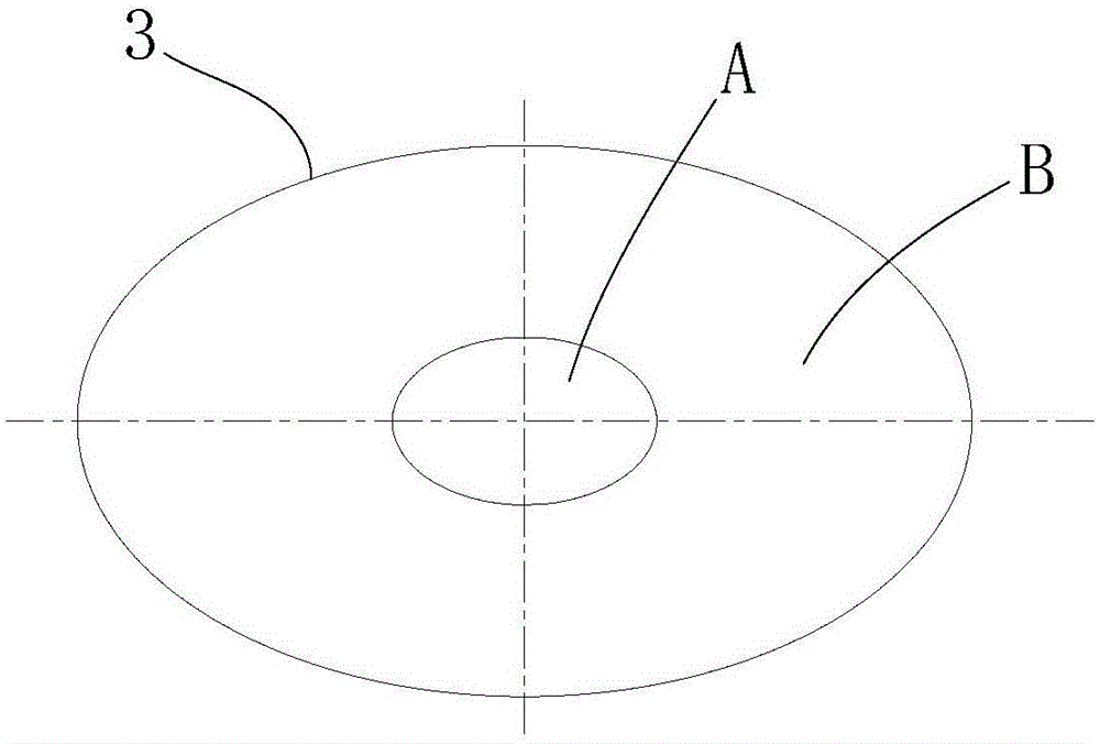
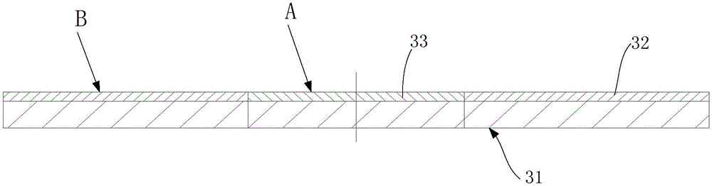
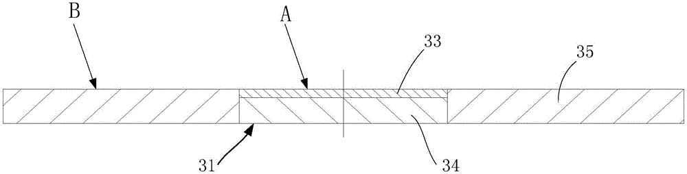
[0044] Such as figure 1 and figure 2 As shown, a beam splitter includes a beam splitter, the beam splitter body 31 has a first area B for reflection and a second area A for light transmission and reflection, and the first area B is a reflection area , the second area A is a transflective area or a polarization splitting area. When in use, the beam emitted by the beam source is irradiated to the target through the second area, and the reflected light of the target is passed through the second area A and the first Area B reflection.
[0045] Such as figure 1 As shown, in this example, the second area A is located in the middle area of the light splitter body 31, and the first area B is located in the outer area of the light splitter body 31; the middle here represents the center of the light splitter body 31, and the outside represents the light splitter The area on the body 31 relative to the central periphery.
[0046] In general, due to the scattering of objects, the...
Embodiment 2
[0056] This example mainly takes the application of the beam splitter in the laser coaxial range finder as an example to describe in detail, such as Figure 7 As shown, a laser coaxial rangefinder includes a laser 1 and a detector 5, and also includes a second lens 2, a beam splitter 3 and a first lens 4 arranged in sequence along the optical axis of the laser 1, wherein the beam splitter 3 adopts In any structure of Embodiment 1, the beam splitter 3 is provided with a semi-transparent and semi-reflective area (or polarization splitting area) and a reflection area, and the light beam emitted by the laser 1 is focused into a thin beam by the second lens 2, and passes through the semi-transparent and semi-reflective area. The reflection area (or polarization splitting area) passes through the first lens 4 to form a parallel beam to irradiate the object 6 to be measured. The light beam reflected by the object 6 to be measured is collected by the first lens 4 and reflected from the...
Embodiment 3
[0063] Such as Figure 8 As shown, in this example, compared with Embodiment 2, the second lens 2 is removed, and the light emitted by the laser 1 is collected by the small hole diaphragm 7 of the shield and then shoots to the beam splitter 3. This structure can also solve the detection blind spot The problem. All the other structures and principles are the same as in Embodiment 2.
[0064] The arrangement of the present invention can be used for laser phase ranging instruments, and can also be used for laser pulse time ranging instruments. This coaxial method can not only realize the detection of long-distance and weakly reflective objects, but also effectively avoid the blind spot problem of specular reflective objects .
[0065] The spectroscopic sheet of the present invention can be applied to the field of optical measurement and observation. The spectroscopic sheet includes a semi-transparent and semi-reflective area and a reflection area. The reflected light is reflec...
PUM
 Abstract
Description
Claims
Application Information
PatSnap Eureka turns technology decisions into work you can execute. Powered by our Innovation Knowledge Graph, it runs expert workflows across engineering, life sciences, materials and intellectual property. Get your review-ready output in minutes.


