Radiometer radio-frequency interference detection method and device based on combination of statistical domain and time-frequency domain

A radio frequency interference, combined time-frequency technology, applied in dosimeters, transmission systems, transmission monitoring and other directions, can solve problems such as the failure of the pulse detection algorithm, the pulse detection algorithm is greatly affected by the brightness temperature change, and the interference detection cannot be completely realized. To achieve the effect of simple implementation, overcoming the problem of detection blind spots, and realizing detection

Inactive Publication Date: 2016-07-27
NANJING UNIV OF SCI & TECH
View PDF4 Cites 4 Cited by
  • Summary
  • Abstract
  • Description
  • Claims
  • Application Information

AI Technical Summary

Problems solved by technology

For example, in the "AKurtosis-Based Approach to Detect RFI in SMOS Image Reconstruction Data Processor" research report, a radiometer radio frequency interference detection method based on kurtosis, a signal statistical characteristic, is proposed. However, the kurtosis detection algorithm has detection blind spots for interference signals with a duty cycle of 50%. Interference detection cannot be fully implemented
As another example, the research report "Time and Frequency Blanking for Radio-Frequency Interference Mitigation in Microwave Radiometry" proposed a radiometer radio frequency interference detection method based on pulse detection algorithm, but the pulse detection algorithm is greatly affected by the change of brightness temperature, and the change of brightness temperature caused by the change of observation scene will make the Pulse detection algorithm fails

Method used


Image

  • Radiometer radio-frequency interference detection method and device based on combination of statistical domain and time-frequency domain
  • Radiometer radio-frequency interference detection method and device based on combination of statistical domain and time-frequency domain
  • Radiometer radio-frequency interference detection method and device based on combination of statistical domain and time-frequency domain

Examples


Embodiment Construction

[0023] In order to better understand the technical content of the present invention, specific embodiments are given together with the attached drawings for description as follows.

[0024] Aspects of the invention are described in this disclosure with reference to the accompanying drawings, which show a number of illustrated embodiments. Embodiments of the present disclosure are not necessarily intended to include all aspects of the invention. It should be appreciated that the various concepts and embodiments described above, as well as those described in more detail below, can be implemented in any of numerous ways, since the concepts and embodiments disclosed herein are not limited to any implementation. In addition, some aspects of the present disclosure may be used alone or in any suitable combination with other aspects of the present disclosure.

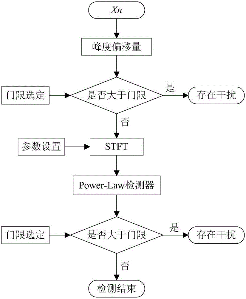
[0025] combine figure 1 As shown, according to an embodiment of the present invention, a radiometer radio frequency ...


PUM


Abstract

The invention discloses a radiometer radio-frequency interference detection method based on a combination of a statistical domain and a time-frequency domain. The radiometer radio-frequency interference detection method comprises the steps: firstly computing a kurtosis offset of a radiometer output signal sample, and judging the existence of radiometer radio-frequency interference through a detection threshold; when the kurtosis offset is smaller than the detection threshold, performing short time Fourier transform, thereby obtaining a spectrogram of a radiometer output signal; performing data processing on the input spectrogram by utilizing a Power Law detector, thereby obtaining output detectable quantity; and comparing the output detectable quantity with the detection threshold, thereby implementing the detection of the radiometer radio-frequency interface. The radiometer radio-frequency interference detection method provided by the invention has the advantages: implementation is simple, no detection blind point exists, no influence of brightness and temperature changes of an observation scene exists, and low-power radio-frequency interface can be detected.

Description

technical field [0001] The invention relates to the field of radio frequency interference signal detection in a wideband passive receiver system, in particular to a radiometer radio frequency interference detection method based on statistical domain joint time-frequency domain. Background technique [0002] A radiometer is a device for measuring the radiation flux of electromagnetic radiation. It is a receiving device with ultra-high sensitivity. It receives the target thermal radiation signal within a specific frequency bandwidth through the antenna to obtain the radiation characteristics of the target, and on this basis realizes the Target detection and identification. The radiometer has good confidentiality, low power and low cost, and has a wide range of applications and good development prospects in many fields such as galaxy detection, ocean remote sensing, and meteorological observation. [0003] Since the expected signal received by the radiometer system comes from ...

Claims


Application Information

Patent Timeline
Patent Type & Authority Applications(China)
IPC IPC(8): H04B17/336H04B17/309G01T1/02H04B17/29H04B17/20
CPCG01T1/02H04B17/20H04B17/29H04B17/309H04B17/336
Inventor 吴礼葛玲玉吕燕彭树生周仁峰肖泽龙
Owner NANJING UNIV OF SCI & TECH
Why Eureka
Try Eureka