Optical device and positioning system of robot

An optical device and robot technology, applied in the field of positioning, can solve the problems of reducing the performance of the robot, unable to respond to the complex and changeable environment in a timely and effective manner, unable to meet the requirements of measurement accuracy and the use of the overall structure at the same time, etc. Use performance, eliminate blind spots, and overcome the effects of detection blind spots

Active Publication Date: 2020-04-21
GUANGDONG BOZHILIN ROBOT CO LTD
View PDF4 Cites 3 Cited by
  • Summary
  • Abstract
  • Description
  • Claims
  • Application Information

AI Technical Summary

Problems solved by technology

[0005] The present invention provides an optical device and a positioning system for a robot to solve the problem that both the common optical axis method and the off-axis method in which the receiving and receiving optical paths are not coaxial can not meet the requirements of measurement accuracy and overall structure at the same time, and cannot be timely and Effectively respond to complex and changeable environments, reduce robot performance and other issues

Method used


Image

  • Optical device and positioning system of robot
  • Optical device and positioning system of robot
  • Optical device and positioning system of robot

Examples


Embodiment Construction

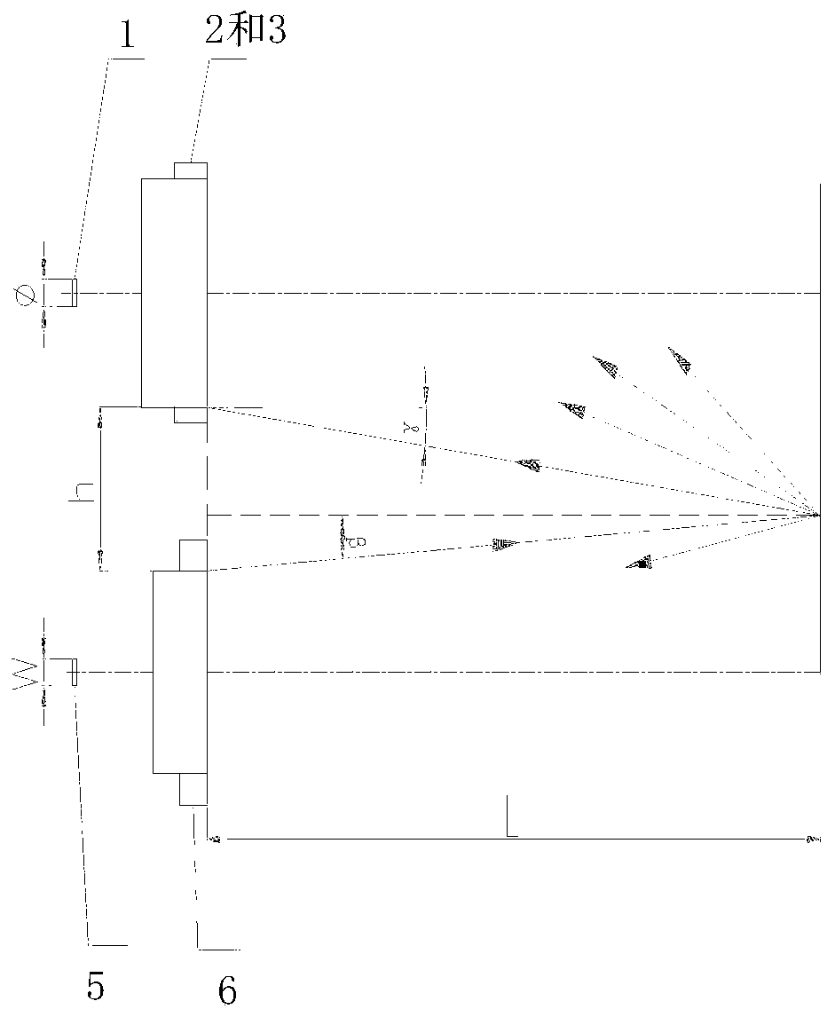
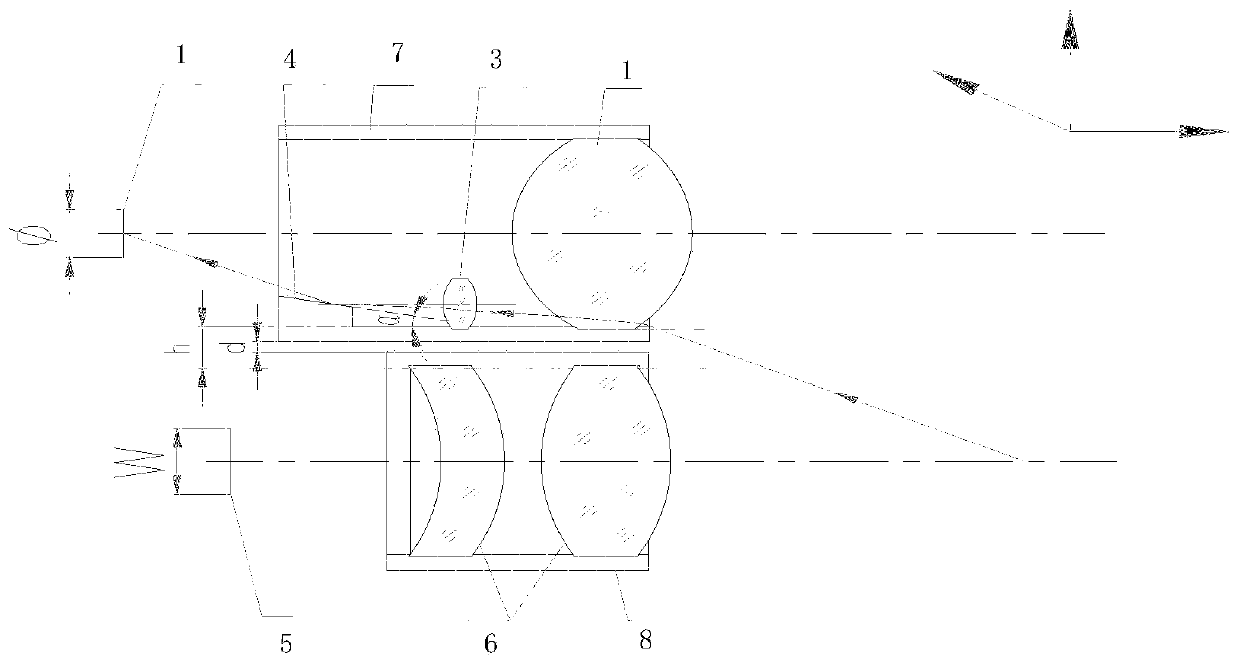
[0013] Embodiments of the present invention are described in detail below, examples of which are shown in the drawings, wherein the same or similar reference numerals designate the same or similar elements or elements having the same or similar functions throughout. The embodiments described below by referring to the figures are exemplary and are intended to explain the present invention and should not be construed as limiting the present invention.

[0014] The following describes the optical device and the positioning system of the robot according to the embodiment of the present invention with reference to the accompanying drawings. Aiming at the problems mentioned in the above-mentioned background technology center that both the common optical axis method and the off-axis method in which the receiving and receiving optical circuits are not coaxial can not meet the measurement accuracy and the use requirements of the overall structure at the same time, the present invention ...


PUM


Abstract

The invention discloses an optical device and a positioning system of a robot. The optical device comprises a transmitting optical assembly and a receiving optical assembly, wherein the transmitting optical assembly is used for transmitting a detection signal; and the receiving optical assembly is not arranged on the same optical axis as the transmitting optical assembly, comprises a detector anda first receiving mirror and a second receiving mirror which are different in focal length, and is used for determining positioning information of the robot according to reflection signals and detection signals of a target object detected by means of the first receiving mirror and a target object detected by means of the second receiving mirror. Therefore, the problems that no matter whether a co-optical-axis mode is adopted or an off-axis mode non-coaxial with a transmitting-receiving optical path is adopted, the use requirements of the measurement precision and the overall structure cannot be met at the same time, complex and variable environments cannot be timely and effectively dealt with, and the use performance of the robot cannot be reduced are solved.

Description

technical field [0001] The invention relates to the technical field of positioning, in particular to an optical device and a positioning system of a robot. Background technique [0002] At present, laser radar, such as the two-dimensional laser radar used in indoor construction robots, is like the human eye, realizing the functions of indoor positioning and obstacle avoidance of robots, but the near-field detection blind spots of laser radar are too many, and it cannot be timely and effectively Coping with the complex and changeable indoor environment will lead to the decline of the performance of indoor construction robots. [0003] In related technologies, the optical path of the two-dimensional laser radar mainly adopts a common optical axis method in which the transmitting and receiving optical paths are on the same axis, and an off-axis method in which the transmitting and receiving optical paths are not coaxial. Among them, the blind area range of the common optical a...

Claims


Application Information

Patent Timeline
IPC IPC(8): G01S17/06G01S17/93G01S7/481
CPCG01S17/06G01S17/93G01S7/4811
Inventor 李璟刘玉平马如豹
Owner GUANGDONG BOZHILIN ROBOT CO LTD
Why Eureka
Try Eureka