
Direct current measuring device

A technology for measuring device and DC current, applied in the direction of measuring device, measuring only current, measuring electrical variables, etc., can solve the problems of limitation, DC input/output characteristics, and difficulty in maintaining single-quality characteristics of DC input/output characteristics, and achieve reliable performance. High performance and high sensitivity

Inactive Publication Date: 2016-04-20
HUAZHONG UNIV OF SCI & TECH
View PDF6 Cites 4 Cited by
  • Summary
  • Abstract
  • Description
  • Claims
  • Application Information

AI Technical Summary

Problems solved by technology

However, this device has the following principle defects: that is, the patent specification states that on the first annular detection core and the second annular detection core, two sets of first modulation detection windings with the same number of turns are respectively wound, and the first excitation The detection winding and the second modulation detection winding, the second excitation detection winding; the two excitation detection windings, the first diode and the second diode, the first resistance and the second resistance and the excitation transformer, constitute the power frequency positive half wave based on The DC current detection system based on the magnetic amplifier principle, the DC input / output characteristics of the detection system based on the magnetic amplifier principle are simple, especially suitable for the detection of large DC current signals
In-depth studies have shown that the DC input / output characteristics of the detection system based on the principle of magnetic amplifiers are difficult to achieve single-quality
Because there are two sets of windings on each of the two ring-shaped detection cores, although they work in the positive half-wave and negative half-wave of the power frequency respectively, the two modulation detection windings, the third diode and the fourth diode and the modulation transformer , the power frequency negative half-wave DC current detection system based on the principle of magnetic modulator is formed. Since the same annular detection core has the effect of mutual coupling on its multi-windings, interference signals will be induced in the two excitation detection windings, and the interference signals are superimposed The DC current detection system based on the principle of a magnetic amplifier makes it difficult to maintain its DC input / output characteristics as a single substance, and its described effects are limited

Method used


Image

  • Direct current measuring device
  • Direct current measuring device
  • Direct current measuring device

Examples


Embodiment Construction

[0021] In order to make the object, technical solution and advantages of the present invention clearer, the present invention will be further described in detail below in conjunction with the accompanying drawings and embodiments. It should be understood that the specific embodiments described here are only used to explain the present invention, not to limit the present invention.

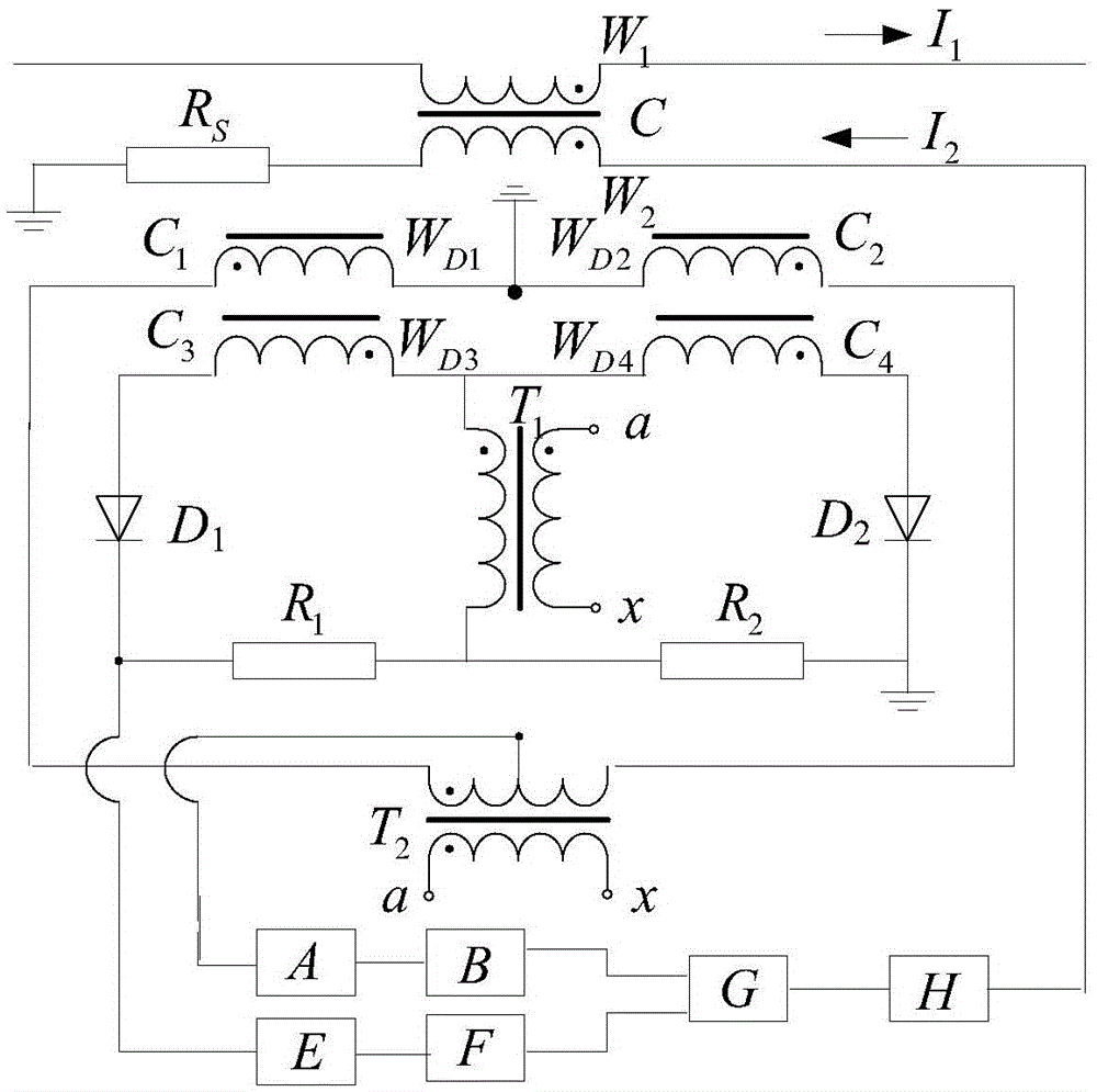
[0022] Embodiments of the present invention include a sensor head, an excitation transformer T 1 , Modulating transformer T 2 , band-pass filter A, phase-sensitive demodulator B, low-pass filter E, DC amplifier F, synthesis regulator G and power amplifier H;

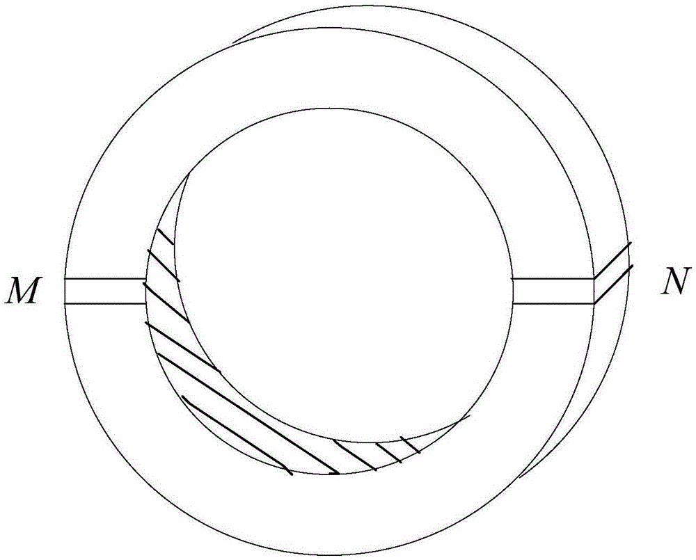
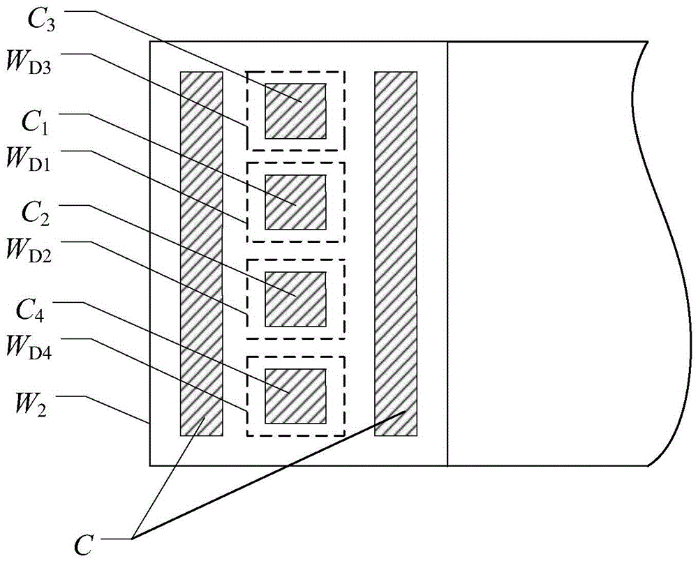
[0023] Such as figure 1 , figure 2 As shown, the sensing head is circular and includes a first annular detection core C 1 , the second annular detection core C 2 , the third annular detection core C 3 , the fourth annular detection core C 4 And annular magnetic shielding core C, four annular detection cores C 1 、C 2 、C 3 、C 4 The ...


PUM


Abstract

The invention relates to a direct current measuring device and belongs to the current measurement equipment electrotechnics field. The direct current measuring device of the invention comprises a sensing head; the sensing head is circular and includes a first annular detection iron core, a second annular detection iron core, a third annular detection iron core and a fourth annular detection iron core; after the first annular detection iron core and the second annular detection iron core which are wound with detecting windings are overlapped with each other, the third annular detection iron core and the fourth annular detection iron core are spliced to two sides of the overlapped first annular detection iron core and second annular detection iron core in an overlapped manner, and an obtained structure is wholly arranged in an annular half-empty cavity formed by the inner layer and outer layer of an annular magnetic shielding iron core; and the outer surface of the annular magnetic shielding iron core is wound with a feedback winding. With the direct current measuring device adopted, accurate measurement of industrial strong direct current of several tens of thousands of amperes can be realized, proportion accuracy can achieve more than two ten thousandths. The system can realize automatic tracking and does not loss balance. The device has the advantages of high stability, high reliability and adaptability to industrial application.

Description

technical field [0001] The invention belongs to the technical field of current measurement in electrotechnical technology, and more specifically relates to a measuring device for direct current. Background technique [0002] The invention patent "DC current measuring device" authorized by the State Intellectual Property Office on May 6, 2015, the patent number: ZL201310199328.6, is original in conception. However, this device has the following principle defects: that is, the patent specification states that on the first annular detection core and the second annular detection core, two sets of first modulation detection windings with the same number of turns are respectively wound, and the first excitation The detection winding and the second modulation detection winding, the second excitation detection winding; the two excitation detection windings, the first diode and the second diode, the first resistance and the second resistance and the excitation transformer, constitute...

Claims


Application Information

Patent Timeline
IPC IPC(8): G01R19/00
CPCG01R19/0092
Inventor 任士焱
Owner HUAZHONG UNIV OF SCI & TECH
Learn More