Liquid crystal display panel and driving method thereof

A technology of liquid crystal display panels and driving methods, applied in static indicators, nonlinear optics, instruments, etc., can solve problems such as high driving power consumption of liquid crystal display panels, affecting the display quality of display panels, and insufficient charging of sub-pixels, etc., to achieve guaranteed Charging effect, elimination of bright streaks, frequency reduction effect of positive and negative polarity inversion

Active Publication Date: 2016-04-20
TCL CHINA STAR OPTOELECTRONICS TECH CO LTD
View PDF7 Cites 52 Cited by
  • Summary
  • Abstract
  • Description
  • Claims
  • Application Information

AI Technical Summary

Problems solved by technology

When the positive and negative polarity of the data signal output by the source drive circuit to the first data line D1 is changed (from positive polarity to negative polarity, or from negative polarity to positive polarity), the first data line D1 There will be a signal delay phenomenon in the uploaded data signal, which will cause insufficient charging of the corresponding sub-pixel, so that the brightness of the light emitted by the corresponding sub-pixel is greater than the ideal brightness. For the first data line D1, the data signal’s The moment of positive and negative polarity switching is at the moment of charging the sub-pixels in the second column, which will cause the brightness of the sub-pixels in the second column to be brighter, thereby forming bright stripes at the position of the sub-pixels in the second column, and so on. A bright stripe will be generated at each data line, and the appearance of the bright stripe will affect the display quality of the display panel and cause a bad user experience. In addition, if figure 2 As shown, the frequency of the inversion signal POL that inverts the positive and negative polarities of the data signal is basically 1 / 2 of the clock signal CLK, and the positive and negative polarities of the data signal need to be changed multiple times within the display period of one frame. The driving power consumption of the liquid crystal display panel is relatively high

Method used


Image

  • Liquid crystal display panel and driving method thereof
  • Liquid crystal display panel and driving method thereof
  • Liquid crystal display panel and driving method thereof

Examples


Embodiment Construction

[0046] In order to further illustrate the technical means adopted by the present invention and its effects, the following describes in detail in conjunction with preferred embodiments of the present invention and accompanying drawings.

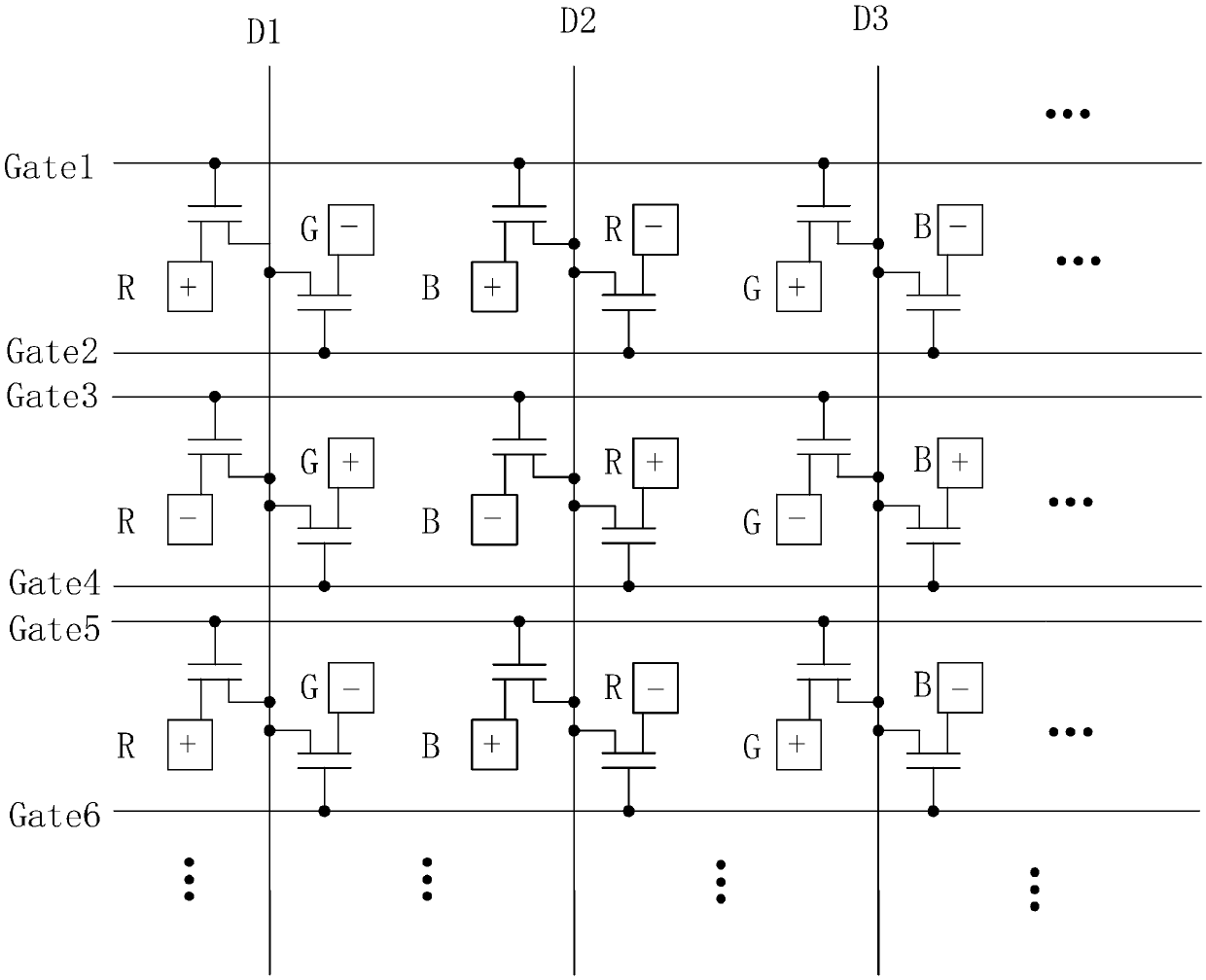
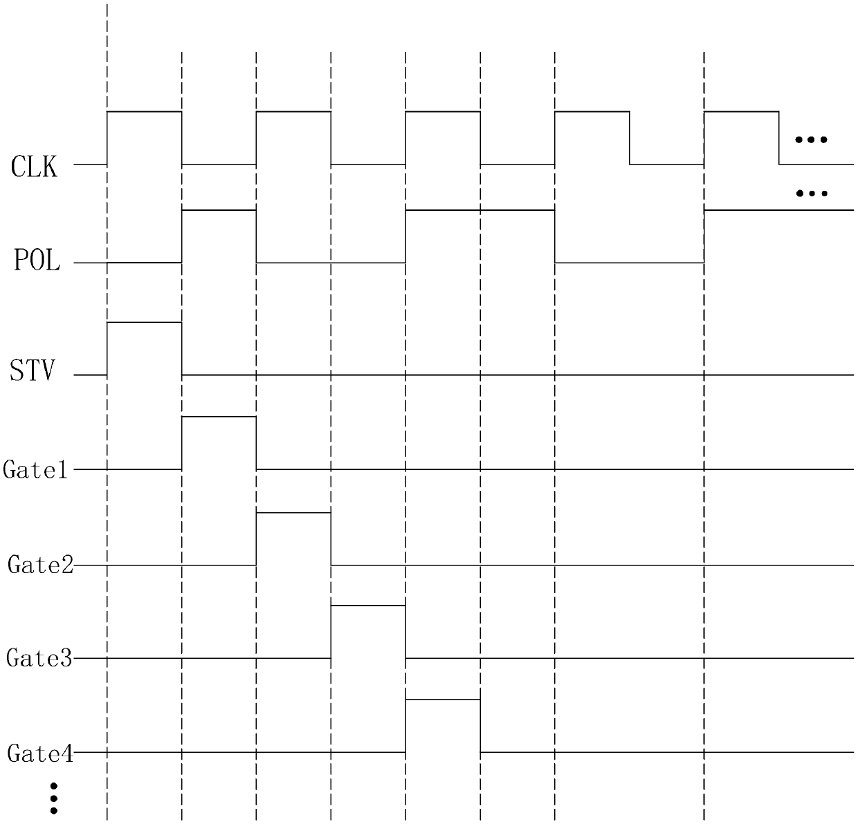
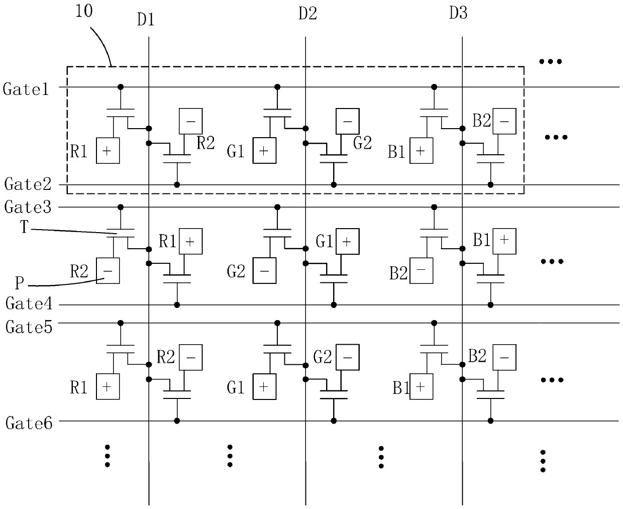
[0047] Please also see image 3 , Figure 4 , the present invention firstly provides a liquid crystal display panel, comprising: a plurality of vertical data lines (such as D1, D2, D3, etc.) (such as Gate1, Gate2, Gate3, Gate4, Gate5, Gate6, Gate7, etc.), and a plurality of pixel units 10 arranged in an array.

[0048] Each pixel unit 10 includes a red pixel module, a green pixel module, and a blue pixel module arranged repeatedly in sequence. The red pixel module includes a first red sub-pixel R1 and a second red sub-pixel R2, the green pixel module includes a first green sub-pixel G1 and a second green sub-pixel G2, and the blue pixel module includes a first blue sub-pixel The color sub-pixel B1 and the second blue sub-pixel B2. Specific...


PUM


Abstract

The invention provides a liquid crystal display panel and a driving method thereof. The 4j grid scanning line and the (4j-3) grid scanning line are set to be odd-number frame grid scanning lines, the (4j-1) grid scanning line and the (4j-2) grid scanning line are set to be even-number frame grid scanning lines, first red subpixels (R1), first green subpixels (G1) and first blue subpixels (B1) are electrically connected to the odd-number frame grid scanning lines, second red subpixels (R2), second green subpixels (G2) and second blue subpixels (B2) are electrically connected to the even-number frame grid scanning lines, odd-number frame scanning and even-number frame scanning are conducted by the odd-number frame grid scanning lines and the even-number frame grid scanning lines respectively, data signal delay can be effectively weakened, the charging effect of all the subpixels is ensured, light fringes of the liquid crystal display panel of the double grid line structure in the display process are eliminated, signal inversion frequency and the driving power consumption of the liquid crystal display panel are reduced.

Description

technical field [0001] The invention relates to the field of display technology, in particular to a liquid crystal display panel and a driving method thereof. Background technique [0002] Liquid Crystal Display (LCD) has many advantages such as thin body, power saving, and no radiation, and has been widely used, such as: LCD TV, mobile phone, personal digital assistant (PDA), digital camera, computer screen or notebook computer Screens, etc., dominate the field of flat panel displays. [0003] Most of the liquid crystal displays currently on the market are backlight liquid crystal displays, which include a liquid crystal display panel and a backlight module. The working principle of the liquid crystal display panel is to pour liquid crystal molecules between the thin film transistor substrate (ThinFilmTransistorArraySubstrate, TFTArraySubstrate) and the color filter substrate (ColorFilter, CF), and apply a driving voltage on the two substrates to control the rotation direc...

Claims


Application Information

Patent Timeline
Patent Type & Authority Applications(China)
IPC IPC(8): G02F1/1362G02F1/1368G02F1/133G09G3/36
CPCG02F1/13306G02F1/136286G02F1/1368G09G3/3648G02F1/1362G02F2201/52G09G3/3614G09G2300/0426G09G2300/0452G09G2310/0224G02F1/134345G02F1/134336G09G3/2074G09G3/36G09G2300/0823
Inventor 徐向阳
Owner TCL CHINA STAR OPTOELECTRONICS TECH CO LTD
Why Eureka
Try Eureka