Shifting register unit, driving method thereof, grid drive circuit and display device

A gate drive circuit, shift register technology, applied in static memory, digital memory information, instruments, etc., can solve the problems of low level, the gate drive signal cannot be maintained, and the gate drive signal cannot be denoised. The effect of improving the effect of noise reduction

Active Publication Date: 2016-04-20
BOE TECH GRP CO LTD +1
View PDF3 Cites 29 Cited by
  • Summary
  • Abstract
  • Description
  • Claims
  • Application Information

AI Technical Summary

Problems solved by technology

[0004] The main purpose of the present invention is to provide a shift register unit and its driving method, a gate drive circuit and a display device to solve the problem that the pull-down time of the gate drive signal is 50% in the output cut-off holding stage in the prior art, and During the time when the gate drive signal is not pulled down, the gate drive signal may not be kept at a low level due to the leakage of the pull-up transistor, so that the gate drive signal cannot be controlled by the existing gate drive signal output module. good noise reduction

Method used


Image

  • Shifting register unit, driving method thereof, grid drive circuit and display device
  • Shifting register unit, driving method thereof, grid drive circuit and display device
  • Shifting register unit, driving method thereof, grid drive circuit and display device

Examples


Embodiment Construction

[0057] The following will clearly and completely describe the technical solutions in the embodiments of the present invention with reference to the accompanying drawings in the embodiments of the present invention. Obviously, the described embodiments are only some, not all, embodiments of the present invention. Based on the embodiments of the present invention, all other embodiments obtained by persons of ordinary skill in the art without making creative efforts belong to the protection scope of the present invention.

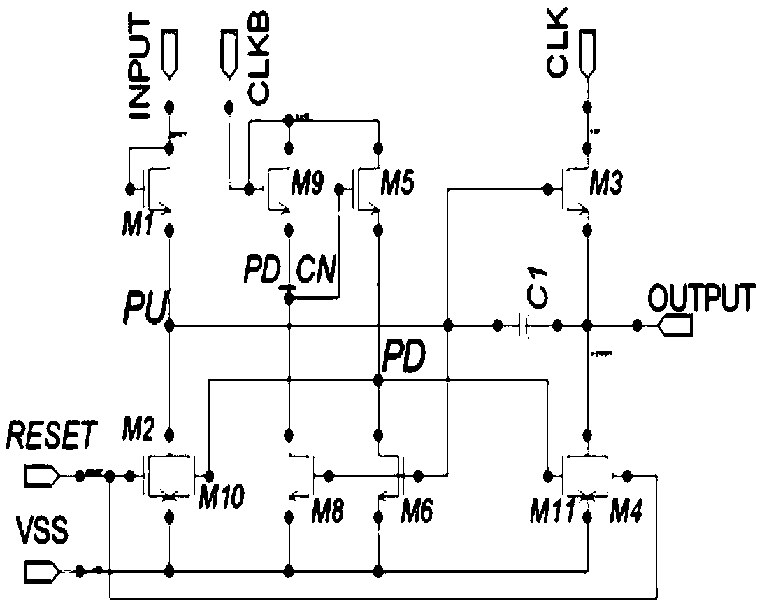
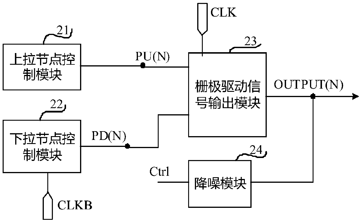
[0058] Such as figure 2 As shown, the shift register unit described in the embodiment of the present invention includes a pull-up node control module 21, a pull-down node control module 22, a gate drive signal output terminal OUTPUT (N) and a gate drive signal output module 23;

[0059] The gate drive signal output module 23 is respectively connected to the pull-up node PU(N), the pull-down node PD(N), the positive-phase clock signal input terminal CLK, and t...


PUM


Abstract

The invention provides a shifting register unit, a driving method thereof, a grid drive circuit and a display device. The shifting register unit comprises a pull-up node control module, a pull-down node control module, a grid drive signal output end and a grid drive signal output module. The grid drive signal output module is connected with a pull-up node, a pull-down node, a normal phase clock signal input end and the grid drive signal output end. The pull-down node control module is connected with the pull-down node and an inverse phase clock signal input end. The shifting register unit further comprises a noise reduction module which is connected with a noise reduction control signal output end and the grid drive signal output end. The noise reduction module controlled by a noise reduction control signal is adopted with the existing grid drive signal output module to control grid drive signal denoising, and the noise reduction effect is improved.

Description

technical field [0001] The present invention relates to the technical field of display driving, in particular to a shift register unit, a driving method thereof, a gate driving circuit and a display device. Background technique [0002] In the existing shift register unit, the pull-down node controls the pull-down gate drive signal during the output cut-off and hold phase, such as Figure 1A As shown, the existing shift register unit only denoises the gate drive signal output terminal OUTPUT through the pull-down node PD, but the waveform of the pull-down node PD in the output cut-off hold phase is the same as the inverted clock input from the inverted clock signal input terminal CLKB The waveforms of the signals are the same, that is, the gate potential of the pull-down transistor M11 for pulling down the gate drive signal is at high level only 50% of the time. because Figure 1A The size of the pull-up transistor M3 is relatively large, so the parasitic capacitance of M3 w...

Claims


Application Information

Patent Timeline
Patent Type & Authority Applications(China)
IPC IPC(8): G09G3/20G11C19/28
CPCG09G3/20G11C19/28G11C7/02G09G3/3266G09G3/3674G09G2330/06G09G2310/0286G11C19/287G09G3/2092G09G2300/0823G09G2310/0289G09G2310/061G09G2310/08G09G2320/02
Inventor 陈华斌
Owner BOE TECH GRP CO LTD
Why Eureka
Try Eureka