
Nuclear power plant integrated in-core instrumentation assembly

A technology for measuring components and nuclear power plants, which is applied in nuclear power generation, nuclear reactor monitoring, reactors, etc., can solve problems such as wear and tear on the support positions of instrument components, increase the number of openings in the lower head of the reactor pressure vessel, and reduce the safety of the reactor design. Safety and the effect of reducing the number of openings

Inactive Publication Date: 2016-04-20
中广核工程有限公司 +1
View PDF5 Cites 14 Cited by
  • Summary
  • Abstract
  • Description
  • Claims
  • Application Information

AI Technical Summary

Problems solved by technology

[0003] However, the above-mentioned measurement method has at least the following defects: first, the core outlet temperature and the neutron flux rate of the core are measured separately using different instrument components, which increases the number of openings in the lower head of the reactor pressure vessel, resulting in a The stiffness of the head is reduced, which leads to a decrease in the safety of the reactor design; secondly, the finger sleeve used to measure the neutron flux rate of the reactor core is introduced from the lower head of the reactor pressure vessel, and it is necessary to open a hole at the bottom of the reactor pressure vessel, which does not comply with The design requirements of advanced reactors (the instruments used to measure the core outlet temperature and neutron flux rate should be located above the core, that is, the instrument components are inserted into the core from the top cover of the reactor pressure vessel); Insertion at the bottom of the reactor pressure vessel, prone to wear at instrumentation assembly support locations

Method used


Image

  • Nuclear power plant integrated in-core instrumentation assembly
  • Nuclear power plant integrated in-core instrumentation assembly

Examples


Embodiment Construction

[0020] In order to make the purpose, technical solution and beneficial technical effects of the present invention clearer, the present invention will be further described in detail below in conjunction with the accompanying drawings and specific embodiments. It should be understood that the specific implementations described in this specification are only for explaining the present invention, not for limiting the present invention.

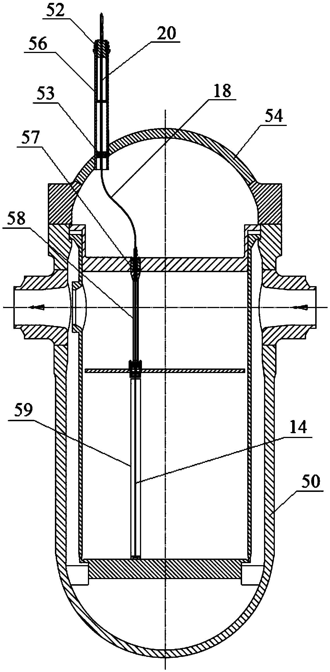
[0021] see figure 1 and figure 2 , the nuclear power plant integrated core measurement assembly of the present invention includes a casing 10 , an upper casing 20 , seven neutron fluence rate measuring devices 30 and a thermocouple 32 .

[0022] The casing 10 is located inside the reactor pressure vessel 50 and is used to ensure that the neutron fluence rate measuring device 30 and the thermocouple 32 are not in contact with the primary loop coolant. Housing 10 includes fitting 12 , transition section 18 , cladding 14 and end plug 16 . The upp...


PUM


Abstract

The invention discloses a nuclear power plant integrated in-core instrumentation assembly. The in-core instrumentation assembly introduces an in-core from a top cover of a reactor pressure vessel, and comprises an upper shell located outside the reactor pressure vessel, a shell located inside the reactor pressure vessel, a plurality of neutron fluence rate measurers used for detecting axial power distribution of the in-core and a thermocouple used for measuring outlet temperature of the in-core; the neutron fluence rate measurers and the thermocouple are all mounted in the shell, and the shell is used for ensuring that the neutron fluence rate measurers and the thermocouple are not in contact with a primary circuit coolant. Compared with the prior art, the nuclear power plant integrated in-core instrumentation assembly provided by the invention introduces the in-core from the top cover of the reactor pressure vessel, and meets the design requirements of advanced reactors; moreover, simultaneous measurement on the outlet temperature of the in-core and the neutron fluence rate of the in-core can be realized, and the trepanning amount of the reactor pressure vessel is reduced, so that the design safety of the reactors can be improved.

Description

technical field [0001] The invention belongs to the field of nuclear power plant core measurement, and more specifically, the invention relates to an integrated nuclear power plant core measurement component. Background technique [0002] Nuclear power plant reactors are equipped with core measuring instruments for measuring core outlet temperature and core neutron flux rate. In known nuclear power plants, the core outlet temperature and the core neutron fluence rate are measured using different types of instrument assemblies. Specifically: the core outlet temperature is measured by 40 thermocouples arranged in the core fuel assembly, the thermocouples are divided into four groups, and the reactor pressure vessel is led out of the reactor pressure vessel through four thermocouple column assemblies; the neutron fluence rate of the core is The measurement is carried out through a finger sleeve equipped with a miniature fission chamber. The insertion end of the finger sleeve i...

Claims


Application Information

Patent Timeline
IPC IPC(8): G21C17/112G21C17/108
CPCG21C17/108G21C17/112Y02E30/30
Inventor 于晓雷张明乾冉小兵刘言午陈永超皮建红曾力
Owner 中广核工程有限公司
Learn More