Single-phase oil-immersed transformer

A transformer and single-phase oil technology, applied in transformer/inductor cooling, transformer/inductor magnetic core, transformer/inductor components, etc., can solve the time-consuming and laborious problems of transformer core maintenance and oil change operations, and achieve Save cost, increase maximum lifting height and reduce cost

Active Publication Date: 2016-04-20
JIANGSU MINGAN ELECTRIC
View PDF8 Cites 3 Cited by
  • Summary
  • Abstract
  • Description
  • Claims
  • Application Information

AI Technical Summary

Problems solved by technology

[0005] In order to overcome the time-consuming and labor-intensive problems of transformer core maintenan

Method used


Image

  • Single-phase oil-immersed transformer
  • Single-phase oil-immersed transformer
  • Single-phase oil-immersed transformer

Examples


Embodiment Construction

[0027] The present invention will be described in further detail below in conjunction with the accompanying drawings and embodiments. It should be understood that the specific embodiments described here are only used to explain the present invention, not to limit the present invention.

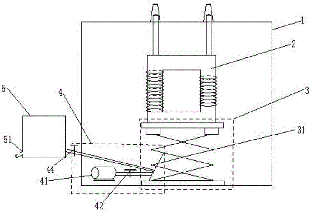
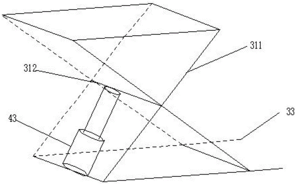
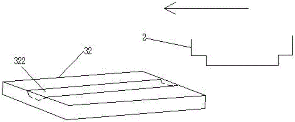
[0028] A single-phase oil-immersed transformer, such as figure 1 As shown, it includes a box body 1 with a box cover, an iron core 2, a coil, a heat dissipation pipe and an oil conservator, wherein the iron core 2 is a single-frame double-stem column, and is arranged in the center of the box body 1 and is immersed in the oil body. Coils are respectively wound on the single-frame double core columns, and the coils are led out of the box cover. The high-voltage insulating bushings and low-voltage insulating bushings are respectively set on the lead wires. The upper end of one side of the body 1, the single-phase oil-immersed transformer also includes a lifting mechanism 3, a power mechanism 4 a...


PUM


Abstract

The invention provides a single-phase oil-immersed transformer which comprises a box body with a box cover, an iron core, coils, radiating tubes and an oil conservator. The iron core is a single-frame double-core column and is arranged at the center of the box body and immersed in oil, the single-frame double-core column is wounded with the coils respectively, the coils are led out of the box cover, leads are respectively sleeved with a high-pressure insulation sleeve and a low-pressure insulation sleeve, the radiating tubes are arranged on the side wall of the box body, and the oil conservator is arranged at the upper end of one side of the box body. The single-phase oil-immersed transformer further comprises a lifting mechanism, a power mechanism and an oil tank, wherein the oil tank is connected with the power mechanism and is arranged outside the box body. The single-phase oil-immersed transformer uses the oil in the box body as a power source through the power mechanism, drives the lifting mechanism to take out the iron core, stores the oil in the box body to the oil tank, facilitates iron core maintenance and oil change operation, saves the cost and also improves the overhaul efficiency.

Description

technical field [0001] The invention relates to the technical field of power transmission equipment, in particular to a single-phase oil-immersed transformer. Background technique [0002] The main components of the transformer are iron core and coil, and the iron core plays the role of magnetic conduction and skeleton in the transformer, and its processing quality directly affects the quality of the transformer. At present, transformer iron cores generally adopt laminated iron core structure, which is different from the manufacture of small transformer iron cores in the manufacturing process, mainly reflected in the stacking and lifting methods of iron cores. Transformer iron cores generally only need to be placed on the working platform After the stacking is completed, it can be lifted directly from the working platform with a sling so that it can be changed from a horizontal position to a vertical position. During the lifting process, it is easy to deform the iron core an...

Claims


Application Information

Patent Timeline
IPC IPC(8): H01F27/14H01F27/06H01F27/26
CPCH01F27/06H01F27/14H01F27/266
Inventor 曹洪新
Owner JIANGSU MINGAN ELECTRIC
Why Eureka
Try Eureka