Eureka AIR delivers breakthrough ideas for toughest innovation challenges, trusted by R&D personnel around the world.

Permanent magnet transmission long-life sealing contactor

A sealed contact, permanent magnet transmission technology, applied in electromagnetic relays, electromagnetic relay details, relays, etc., can solve the problem that the contactor does not have the function of vacuum arc extinguishing, the driving power consumption and holding power consumption are large, and the overall size of the contactor is large. and other problems, to achieve the effect of reducing electromagnetic suction requirements, reducing power consumption, and simple and reliable structure

Inactive Publication Date: 2016-04-20
DAQING CANBO ELECTRIC APPLIANCE CO LTD
View PDF9 Cites 0 Cited by
  • Summary
  • Abstract
  • Description
  • Claims
  • Application Information

AI Technical Summary

Problems solved by technology

The disadvantages of the existing contactors are: 1. Most of the existing contactors do not have the vacuum arc extinguishing function. The existing contactors with the vacuum arc extinguishing function use an independent vacuum interrupter for arc extinguishing. The service life of the arc chamber is short, the supporting action mechanism is complicated, and the manufacturing cost is high
2. Since the electromagnet directly drives the moving contact, the electromagnetic attraction required is relatively large, resulting in a relatively large size of the electromagnetic coil, which in turn leads to a relatively large overall size of the contactor; at the same time, the larger electromagnetic coil also makes the driving power larger. Power consumption and hold power are also relatively large

Method used


Image

  • Permanent magnet transmission long-life sealing contactor
  • Permanent magnet transmission long-life sealing contactor

Examples


Embodiment Construction

[0016] The present invention will be further described below in conjunction with accompanying drawing:

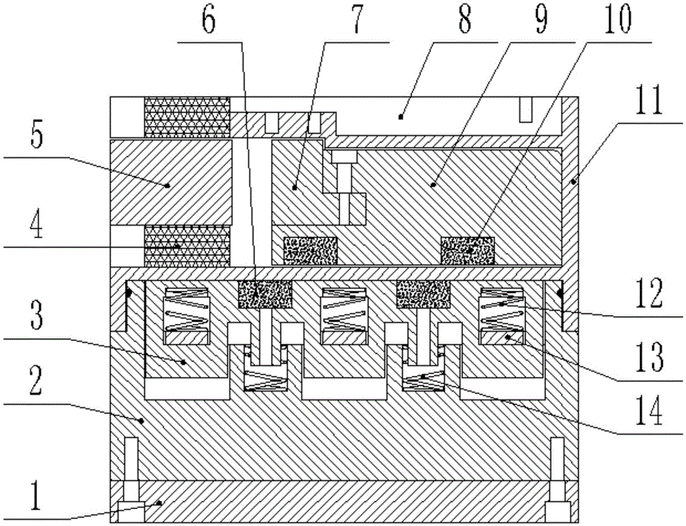
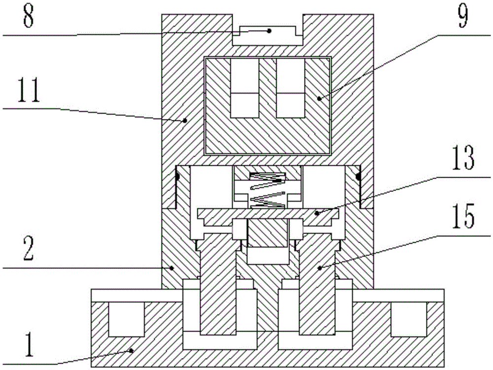
[0017] This embodiment includes a housing, the housing is provided with a static main contact 15 and a moving main contact 13, the static main contact 15 is fixed on the bottom inside the housing, and the moving main contact 13 is installed on the slave On the moving frame 3, the driven frame 3 slides up and down so as to realize the contact or separation of the static main contact 15 and the moving main contact 13; the casing includes an upper casing 11 and a lower casing 2, and the upper casing 11 and The lower shells 2 are airtightly connected to form a closed vacuum chamber after the air is drawn out, and the driven frame 3 is set in the vacuum chamber, and a driven frame return spring is arranged between the driven frame 3 and the lower shell 2 14. The contact surfaces of the driven frame 3 and the lower casing 2 are staggered to form three independent vacuum interrupt...


PUM


Abstract

The invention belongs to the technical field of contactors, and particularly relates to a permanent magnet transmission long-life sealing contactor. The permanent magnet transmission long-life sealing contactor comprises a shell. A static main contact and a dynamic main contact are arranged inside the shell. The shell comprises an upper shell body and a lower shell body. The upper shell body and the lower shell body are in sealed connection, and air is pumped out to form a closed vacuum cavity. A driven frame is arranged inside the vacuum cavity. A driven frame reset spring is arranged between the driven frame and the lower shell body. The contact faces of the driven frame and the lower shell body are matched in a staggered mode to form three independent vacuum arc-extinguishing chambers. A driven permanent magnet is arranged on the upper side of the driven frame. A static iron core and a movable iron core opposite to each other in position are arranged inside the upper shell body. An electromagnetic coil is arranged on the outer side of the static iron core. The movable iron core is installed on a driving frame which can horizontally slide inside the upper shell body. A driving permanent magnet corresponding to the driven permanent magnet is arranged on the lower side of the driving frame. The permanent magnet transmission long-life sealing contactor is long in service life and low in power consumption.

Description

technical field [0001] The invention belongs to the field of contactors, in particular to a permanent magnet transmission long-life sealing contactor. Background technique [0002] A contactor is a circuit control device that uses a coil to flow current in a circuit to generate a magnetic field to close the contacts to control the load. The working principle of an ordinary contactor is: when the coil of the contactor is energized, the coil current will generate a magnetic field, and the generated magnetic field will cause the static iron core to generate electromagnetic attraction, attract the moving iron core to move, and directly drive the moving contact to move, making the normally closed contact When the coil is powered off, the electromagnetic attraction disappears, and the armature is released under the action of the release spring to restore the contact, the normally open contact is disconnected, and the normally closed contact is closed. The disadvantages of the exi...

Claims


Application Information

Patent Timeline
Patent Type & Authority Applications(China)
IPC IPC(8): H01H50/02H01H50/58
CPCH01H50/023H01H50/58
Inventor 程明福程书民
Owner DAQING CANBO ELECTRIC APPLIANCE CO LTD
Why Eureka
Eureka Blog
Learn More