Power supply and control method used for optical switching device

A technology of an optical switching device and a control method, applied in the field of communication, to achieve the effect of saving power interface, eliminating potential damage and simple control method

Inactive Publication Date: 2016-04-20
北京浩瀚深度信息技术股份有限公司
View PDF4 Cites 0 Cited by
  • Summary
  • Abstract
  • Description
  • Claims
  • Application Information

AI Technical Summary

Problems solved by technology

[0004] In order to solve the aforementioned problems, that is, to solve the problems caused by the use of independent power interfaces in existing optical switching devices, the present invention provides a communication device

Method used


Image

  • Power supply and control method used for optical switching device
  • Power supply and control method used for optical switching device
  • Power supply and control method used for optical switching device

Examples


Embodiment Construction

[0016] Preferred embodiments of the present invention are described below with reference to the accompanying drawings. Those skilled in the art should understand that these embodiments are only used to explain the technical principle of the present invention, and are not intended to limit the protection scope of the present invention. For example, although the present application is described in conjunction with DPI, the technical solutions of the present invention can also be applied to any other occasions where an optical switching device is provided, and such changes should not limit the present invention.

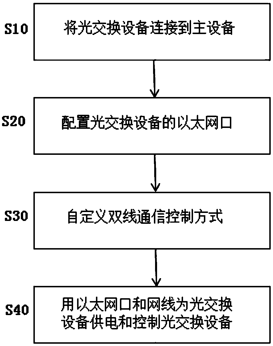
[0017] First refer to figure 1 , which is a flowchart of a power supply and control method for an optical switching device according to the present invention. The optical switching device of the present invention is set in a communication device, and the communication device also includes a master device. Such as figure 1 As shown, the method of the present invention...


PUM

PropertyMeasurementUnit
Lengthaaaaaaaaaa

Abstract

The invention relates to the field of communication, and specifically provides a power supply and control method used for an optical switching device. The power supply and control method used for the optical switching device aims at solving problems caused by utilization of independent power interfaces of the existing optical switching device. For the purpose, the optical switching device is arranged in a communication device; the communication device also comprises a primary device; and the power supply and control method used for the optical switching device comprises the steps of directly connecting the optical switching device to the primary device through an Ethernet interface and an Ethernet line; and enabling the optical switching device to get electricity from the primary device. Technicians in the field are easy to understand that the optical switching device is not provided with any independent power supply interface but is directly connected with the primary device through the Ethernet line and the Ethernet interface so as to get the electricity from the primary device, so that a power interface in a communication frame is not only saved, but the optical switching device also can realize state switching of Bypass rapidly when the primary device is accidently in power failure; and the control way is simple and reliable.

Description

technical field [0001] The invention relates to the communication field, and specifically provides a power supply and control method for optical switching equipment. Background technique [0002] DPI (Deep Packet Inspection), that is, deep packet analysis technology is a traffic detection and control technology based on the application layer. When the IP data packet, TCP or UDP data flow passes through the bandwidth management system based on DPI technology, the system reads the The content of the packet load is used to reorganize the application layer information in the OSI seven-layer protocol, so as to obtain the content of the entire application program, and then perform traffic shaping operations according to the management strategy defined by the system. The application types that can be identified by the bandwidth management solution based on DPI technology must be known to the system. Taking BT, which is well-known to users, as an example, the protocol feature word o...

Claims


Application Information

Patent Timeline
IPC IPC(8): H04L12/10
CPCH04L12/10
Inventor 黄少杰张琨刘明华
Owner 北京浩瀚深度信息技术股份有限公司
Why Eureka
Try Eureka