Supercharge Your Innovation With Domain-Expert AI Agents!

Temperature monitoring device for electrical equipment of power grid and monitoring method thereof

A technology for electrical equipment and monitoring devices, which is applied in the field of temperature monitoring devices for electrical equipment in power grids. It can solve problems such as damage to temperature collection nodes, disorderly transmission, and traffic jams in the transmission of temperature signals, so as to recover the loss of human, material and financial resources and prevent fires. As well as the effect of electric shock and avoiding traffic jams

Inactive Publication Date: 2016-04-20
武汉供电变压器修造有限公司
View PDF5 Cites 6 Cited by
  • Summary
  • Abstract
  • Description
  • Claims
  • Application Information

AI Technical Summary

Problems solved by technology

However, since there are many terminals to be tested, and most of them are distributed in areas with harsh climate conditions, the location distribution is relatively complicated, so the temperature collection nodes located at each terminal are very cumbersome to arrange, and the inherent temperature collection nodes of each terminal are often affected by Damaged or slightly moved by the surrounding environment, "traffic jam" occurs when transmitting temperature signals, and the transmission is also very chaotic, which greatly reduces the efficiency and stability of temperature measurement accuracy. For monitoring data and historical status work Personnel often can only be consulted and retrieved in the monitoring center, and cannot be consulted and retrieved in the field or outside the monitoring center. Moreover, due to the limited hardware conditions of the mobile phone, it is basically impossible to use the browser in the mobile phone to directly call the local authentication system. Impossible, you have to develop a special browser security plug-in

Method used


Image

  • Temperature monitoring device for electrical equipment of power grid and monitoring method thereof

Examples


Embodiment Construction

[0028] The present invention will be further described below in conjunction with specific embodiment:

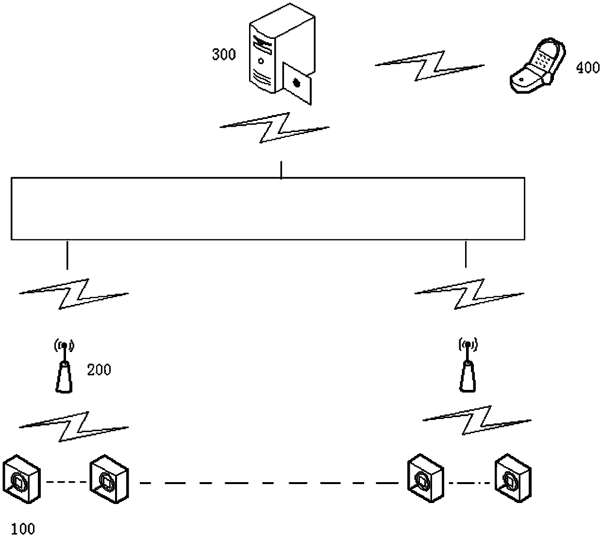
[0029] A temperature monitoring device for electrical equipment in a power grid, comprising the following parts: a data collection node 100 for collecting equipment temperature signals; a central node 200 for receiving, storing and uploading the collected equipment temperature signals; a control host 300 for Control the operation of the temperature monitoring device; the mobile phone 400 is used to remotely query the temperature status of the equipment, and the data acquisition node 100 communicates with the central node 200, and the central node 200 communicates with the control host 300. The control host 300 communicates with the mobile phone 400.

[0030] The data acquisition node 100 and the central node 200 communicate and interact through the WSN or TDMA protocol, and the central node 200 and the control host 300 communicate and interact through RS-232 or RS-485, and t...


PUM


Abstract

The invention discloses a temperature monitoring device for electrical equipment of a power grid and a monitoring method thereof. The device comprises data acquisition nodes, center nodes, a control host and a mobile phone. The method comprises the steps of carrying out networking on the data acquisition nodes, the center nodes, the control host and the mobile phone through Internet of Things and the like. The device and the method have the following advantages that the device utilizes the data acquisition nodes based on the digital wireless temperature to carry out real-time detection on a temperature anomaly condition caused by overload, poor heat dissipation and climate reasons of various electrical equipment of the power grid in operations of power transmission and transformation and power generation and distribution, so that fire and electric shock which are caused by temperature anomaly of the electrical equipment of the power grid can be prevented to recover the losses of manpower, material resources and financial resources for the nation.

Description

technical field [0001] The invention belongs to the technical field of electric equipment monitoring. In particular, it relates to a temperature monitoring device and a monitoring method for electrical equipment in a grid. Background technique [0002] During the 12th Five-Year Plan period, the motherland’s economy maintained a medium-to-high speed development, and the power supply load of the power grid is also increasing. As the highlight of the safety of electrical equipment in the grid, the temperature monitoring of electrical equipment in the grid has become the focus of the work of power companies in various places. Fires caused by abnormal temperatures in electrical equipment in the grid And contact accidents occur from time to time, resulting in the loss of human, material and financial resources. Therefore, it is very important to monitor the temperature of electrical equipment in the power grid accurately, quickly and in real time. However, since there are many te...

Claims


Application Information

Patent Timeline
IPC IPC(8): H04L29/08G01K1/02G08C17/02G06Q50/06G01K1/024
CPCH04L67/12G06Q50/06G08C17/02G01K1/024
Inventor 曾正扬
Owner 武汉供电变压器修造有限公司
Features
  • R&D
  • Intellectual Property
  • Life Sciences
  • Materials
  • Tech Scout
  • Unparalleled Data Quality
  • Higher Quality Content
  • 60% Fewer Hallucinations
Learn More