
Continuously variable drivetrain

a drivetrain and continuous variable technology, applied in the direction of folding cycles, cycle equipment, etc., can solve the problems of linear drive systems in human powered vehicles, ineffective as commonly used drivetrains, and loss of kinetic energy of drivetrains

Inactive Publication Date: 2008-03-27
CATADON SYST
View PDF98 Cites 50 Cited by
  • Summary
  • Abstract
  • Description
  • Claims
  • Application Information

AI Technical Summary

Benefits of technology

"The systems and methods described in this patent have several features that make them useful. These features are not solely responsible for the system's desirable attributes, but they are important nonetheless. The technical effects of this patent are that it provides a way to manage and control computer networks, which can improve efficiency and reliability. It also provides a way to securely store and access data, which can protect sensitive information. Overall, this patent offers a way to create better and more secure computer systems."

Problems solved by technology

All of these drivetrains suffer from a loss of kinetic energy at the end of each stroke.
Linear drive systems in human powered vehicles have been attempted many times. However, they are not as efficient as commonly used drivetrains, such as sprocket and chain systems used on bicycles, due to the loss of kinetic energy at the end of each stroke.
Many of the human powered linear drive systems are also complex, and each gear, bearing, pulley, cable, chain, or sprocket used in the drivetrain reduces efficiency.
The complex systems are also heavy, and weight is a significant factor in human powered vehicles because it increases inertia and power requirements.
Complex systems are also more expensive and more prone to breaking.
However, power is only efficiently created through about 60 degrees of the stroke, and only becomes very efficient for about 30 degrees of the 360 degree rotary stroke.
This stroke also creates two large torque spikes per revolution.
However, the majority of people are not comfortable pedaling at a high speed and consequently do not maintain a cadence which maximizes the efficiency inherent in a bicycle's rotary stroke.
Further, the most common complaint from individuals riding bicycles is discomfort created by the bike seat.
Recent studies showing that bicycle riding contributes to impotence and other health problems aggravate the discomfort problem caused from bike seats.
However, maximizing the efficiency inherent in the bicycle drivetrain requires that the user stay seated while pedaling.
The second most common complaint among bicycle users is difficulty when shifting.
While this is rarely a problem with avid cyclists, infrequent users routinely shift in the wrong direction, shifting to a higher gear when starting up a hill, or vice versa.
This problem can lead to the chain coming off of a sprocket, binding of the chain, a broken chain, and in rare cases the user getting injured in a fall.
The problem frustrates enough people that it reduces the percentage of the population that ride a bicycle.

Method used


Image

  • Continuously variable drivetrain
  • Continuously variable drivetrain
  • Continuously variable drivetrain

Examples


Embodiment Construction

” one will understand how the features of the system and methods provide several advantages over traditional systems and methods.

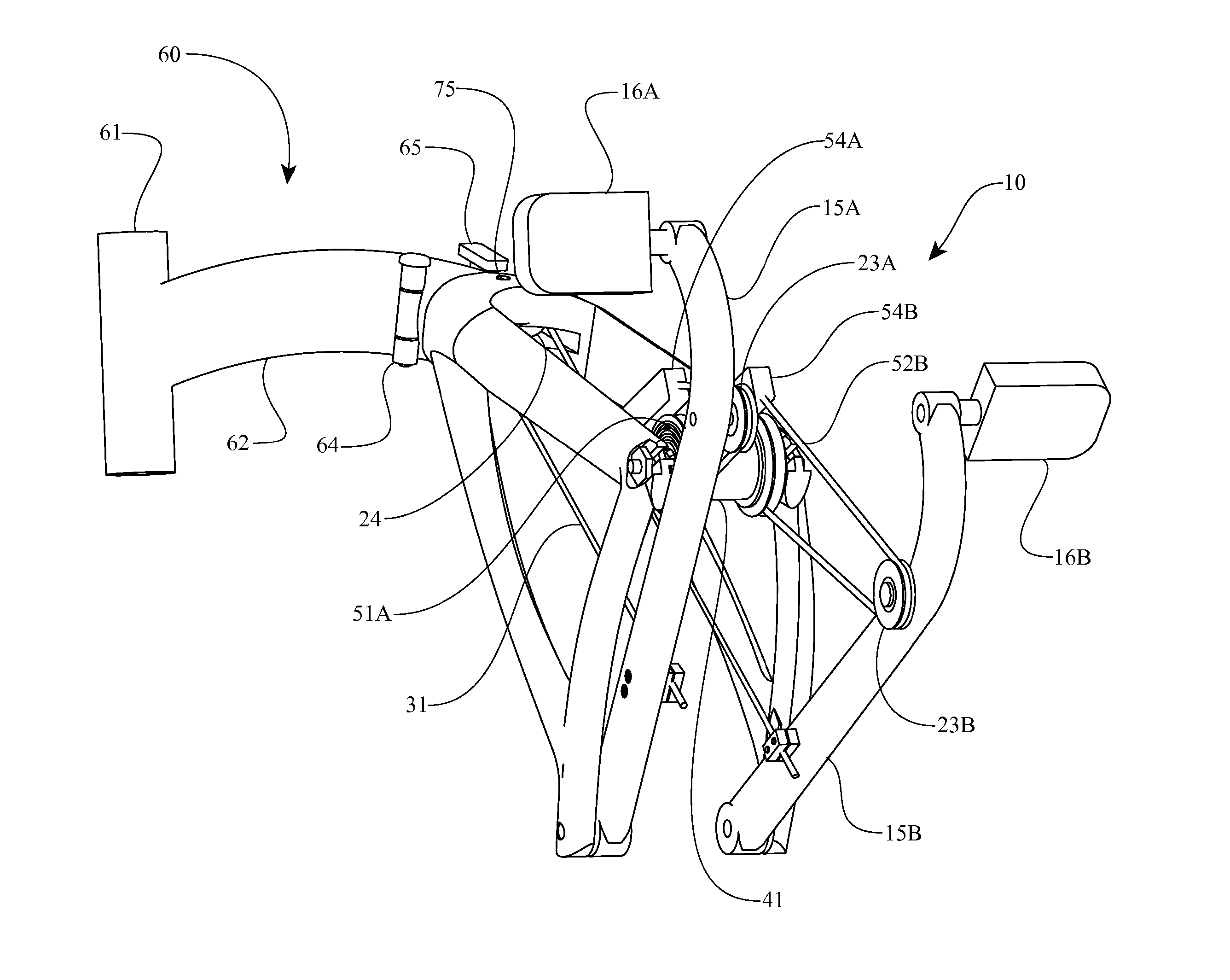
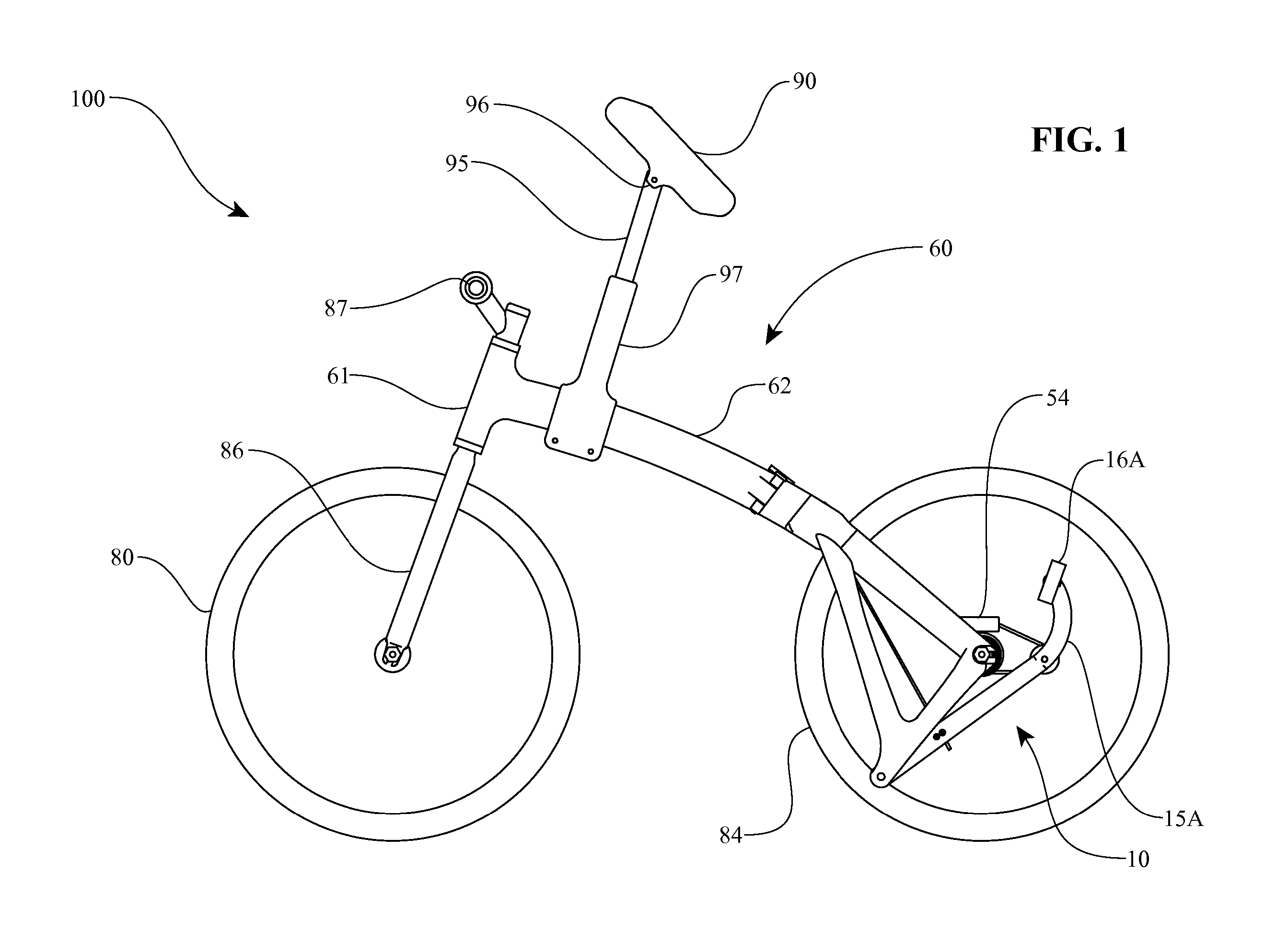
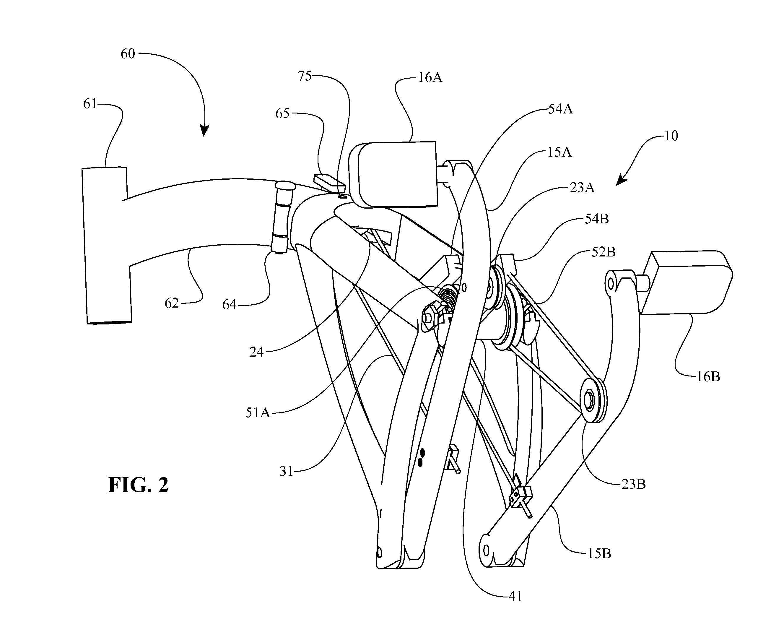
[0015] In one aspect, a pulley and cable drivetrain is disclosed which continuously varies speed and torque throughout its stroke. In some systems the continuously variable drivetrain incorporates two pedals, which are contacted by a person's feet, and move in reciprocating motion to transmit power. Each pedal attaches to a crank which rotates along an arc defined by a pivot point at an end opposite the pedal. The cranks attach to a frame, which in some systems comprises the support structure for a human powered vehicle or exercise equipment. Also attached to each crank is a pulley, the pulley positioned at a distance from the crank pivot point to produce the correct rotational speed of a drive pulley. The drive pulley, of which there is one for each crank, has a drive cable wrapped around a deep annular groove. The drive cable terminates at the interior o...


PUM


Abstract

Drivetrains and frames for vehicles, equipment, machines, etc. Some embodiments of the drivetrains and frames are particularly suited for human powered machines, such as bicycles and exercise equipment. In some embodiments, a drivetrain includes a reciprocating crank coupled to a crank pivot. A lever couples to the crank via a lever pivot positioned on the crank. A lever stop cooperates with a lever guide surface to guide a motion of the lever as the lever pivots about the lever pivot. The lever and / or the crank are operably coupled to a drive pulley, idler pulley, and / or compound pulley. In some embodiments, a drive cable operably couples the lever and / or the crank to the drive pulley, idler pulley, and / or the compound pulley. In one embodiment, one or more pulleys couple to the lever's distal ends. In some embodiments, the drivetrain includes a wheel hub adapted to receive torque from the crank via a drive pulley.

Description

RELATED APPLICATIONS [0001] This application is a continuation of U.S. patent application Ser. No. 11 / 747,068, filed on May 10, 2007, which claims priority to U.S. Provisional Patent Application 60 / 799,601, filed on May 11, 2006. The entire disclosure of each of the above applications is hereby incorporated by reference in its entirety. [0002] This application is related to U.S. patent application Ser. No. ______, Attorney Docket No. LINEARB.031C1, U.S. patent application Ser. No. ______, Attorney Docket No. LINEARB.031C2, U.S. patent application Ser. No. ______, Attorney Docket No. LINEARB.031C3, U.S. patent application Ser. No. ______, Attorney Docket No. LINEARB.031C4, U.S. patent application Ser. No. ______, Attorney Docket No. LINEARB.031C5, U.S. patent application Ser. No. ______, Attorney Docket No. LINEARB.031C6, U.S. patent application Ser. No. ______, Attorney Docket No. LINEARB.031C8, and U.S. patent application Ser. No. ______, Attorney Docket No. LINEARB.031C9, all file...

Claims


Application Information

Patent Timeline
Patent Type & Authority Applications(United States)
IPC IPC(8): F16H9/00B60B27/00B62K3/00B62M11/00B62M1/24
CPCB62J1/28B62K3/005B62K3/10B62K15/006Y10T74/20582F16H9/02Y10T74/18232Y10T74/2164B62M1/28
Inventor MILLER, DONALDCROSS, MICHAEL C.
Owner CATADON SYST
Learn More