A video coding method and device

A video encoding and component technology, which is applied in the field of image processing, can solve the problems of high encoding complexity and long time required for video encoding, and achieve the effects of reducing the number of recursive traversals, saving time, and reducing complexity

Active Publication Date: 2018-09-28
ZHEJIANG DAHUA TECH CO LTD
View PDF2 Cites 0 Cited by
  • Summary
  • Abstract
  • Description
  • Claims
  • Application Information

AI Technical Summary

Problems solved by technology

[0008] Embodiments of the present invention provide a video coding method and device to solve the problems existing in the prior art that require a long time for video coding and high coding complexity due to recursive traversal of all TUs of different sizes.

Method used


Image

  • A video coding method and device
  • A video coding method and device
  • A video coding method and device

Examples


Embodiment 1

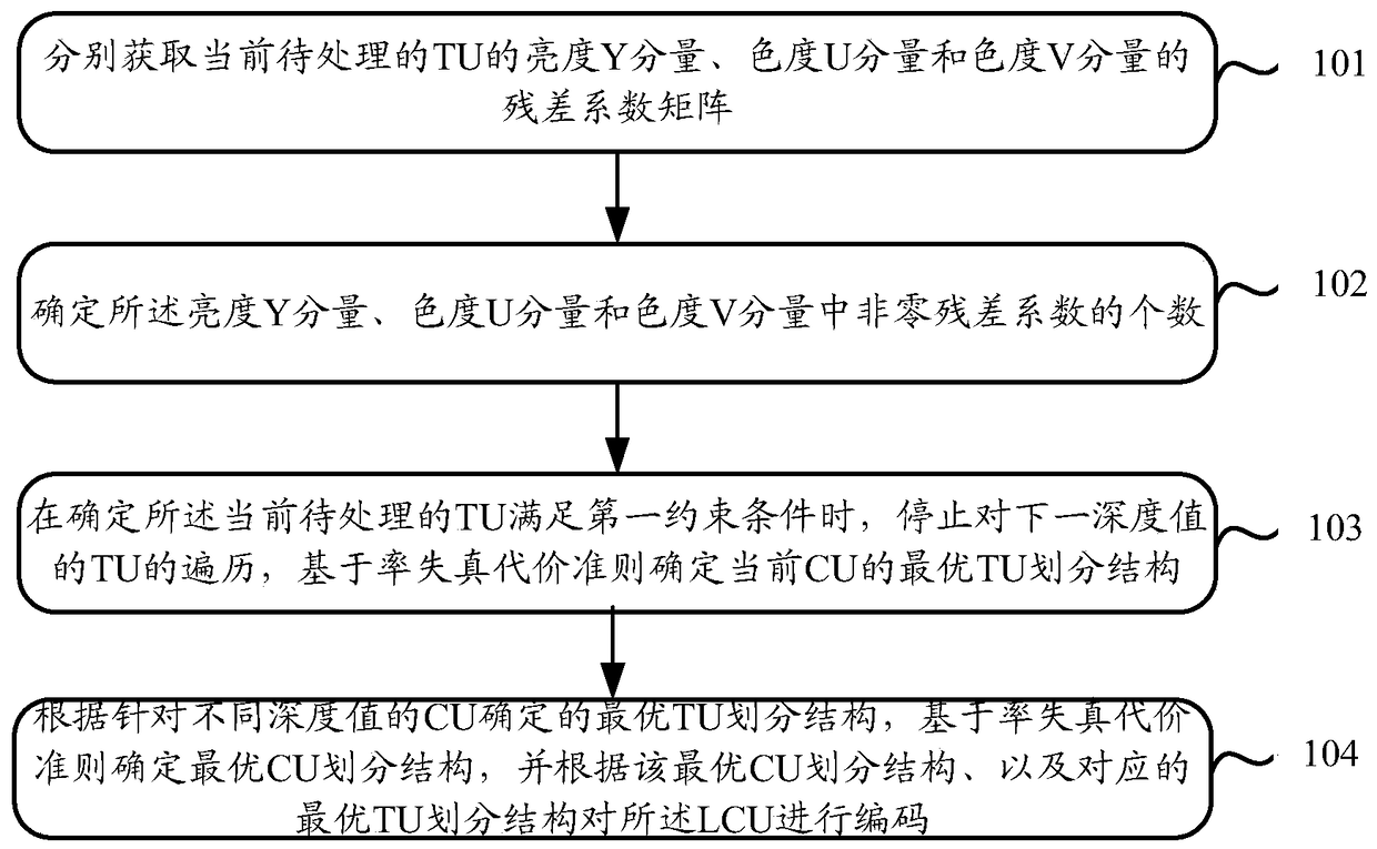
[0037] like figure 2 As shown, it is a schematic flowchart of a video encoding method provided by Embodiment 1 of the present invention, which mainly includes the following steps:

[0038]Step 101: Obtain the residual coefficient matrices of the luma Y component, chrominance U component and chrominance V component of the current TU to be processed for the coding units CU with different depth values ​​in the current largest coding unit LCU determined in the video frame.

[0039] Sub-step 102: Determine the number of non-zero residual coefficients in the luma Y component, chrominance U component and chrominance V component.

[0040] Sub-step 103: When it is determined that the TU currently to be processed satisfies the first constraint condition, stop traversing the TU of the next depth value, and determine the optimal TU partition structure of the current CU based on the rate-distortion cost criterion; wherein, the The first constraint condition is: the CBF value of any two c...

example 1

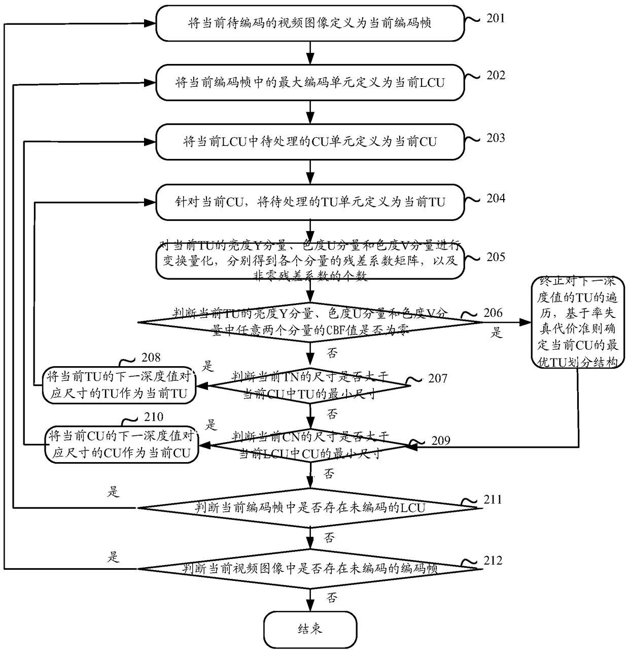
[0059] like image 3 As shown, it is a schematic flow chart of a video coding method provided by Example 1 of the present invention, which specifically includes:

[0060] Step 201: Define the current video image to be encoded as the current encoding frame.

[0061] Since video encoding is performed on each frame of image, and the processing method of each frame of image is similar, only the currently selected video image to be encoded is processed.

[0062] Step 202: Define the largest coding unit in the current coding frame as the current LCU, and define the size range of the CU in the current LCU as: {MaxCUsize, MinCUsize}, and the depth value of the CU is CI.

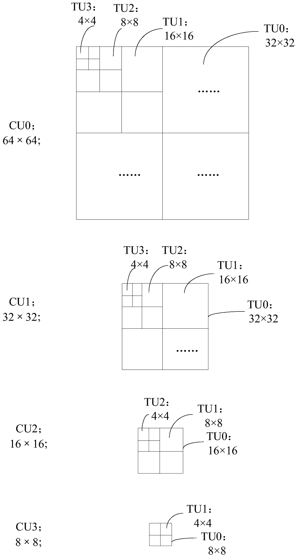
[0063] Assuming that the size of the current LCU is 64×64, then the size range of the CU in the current LCU is: {64×64, 8×8}, and the range of the depth value of the CU is: {0, 3}.

[0064] Step 203: Define the CU unit to be processed in the current LCU as the current CU, and define the size of the current CU as CN...

example 2

[0081] like Figure 4 As shown, it is a schematic flow chart of a video encoding method provided by Example 2 of the present invention, which specifically includes:

[0082] Step 301: Define the current video image to be encoded as the current encoding frame.

[0083] Step 302: Define the largest coding unit in the current coding frame as the current LCU, and define the size range of the CU in the current LCU as: {MaxCUsize, MinCUsize}, and the depth value of the CU is CI.

[0084] Step 303: Define the CU unit to be processed in the current LCU as the current CU, and define the size of the current CU as CN.

[0085] Step 304: For the current CU, define the TU unit to be processed as the current TU, and define the size of the current TU as TN.

[0086] Step 305: Transform and quantize the luma Y component, chrominance U component, and chrominance V component of the current TU to obtain the residual coefficient matrix of each component and the number of non-zero residual coeff...


PUM


Abstract

The invention discloses a video coding method and a video coding device. The video coding method is characterized in that the following steps can be carried out sequentially by aiming at coding units CU having different depth values of a determined current largest coding unit LCU in a video frame: residual coefficient matrixes of brightness Y components, chroma U components, and chroma V components of transformation units TU to be processed can be acquired respectively, and the number of the non-zero residual coefficients of the brightness Y components, chroma U components, and chroma V components can be determined; when the TU to be processed is determined to be capable of satisfying the condition that the CBF values of any two components of the brightness Y components, chroma U components, and chroma V components of the TU to be processed are zero, the recursive traversal of the TU can be stopped. The optimal CU division structure can be determined based on the rate-distortion cost criteria, and the coding of the LCU can be carried out according to the optimal CU division structure, and therefore the times of the recursive traversal can be reduced, the time required by the coding can be saved, and the coding complexity can be reduced.

Description

technical field [0001] The present invention relates to the technical field of image processing, in particular to a video encoding method and device. Background technique [0002] With the rapid development of digital video technology and users' high standard requirements for video quality, video applications are gradually developing in the direction of high definition, high frame rate and high compression rate. For this reason, the JCT-VC working group formulated the High Efficiency Video Coding (HEVC) standard to solve the impact of the sharply increasing data rate of high-definition video and ultra-high-definition video on network transmission. [0003] In the HEVC standard, a lot of improvements and innovations have been made to the coding technology, such as high-precision motion compensation technology, multi-angle intra-frame prediction technology, motion estimation fusion technology and adaptive offset filtering technology, etc. Compared with the H.264 standard, The...

Claims


Application Information

Patent Timeline
Patent Type & Authority Patents(China)
IPC IPC(8): H04N19/122H04N19/147H04N19/186
Inventor 王叶群林聚财张兴明
Owner ZHEJIANG DAHUA TECH CO LTD
Why Eureka
Try Eureka