Centrifuge and method for centrifuging a reaction vessel unit

A reaction vessel and centrifuge technology, applied in the field of centrifuges, to reduce the risk of cross-contamination and achieve the effect of small platform space

Active Publication Date: 2016-04-20
YANTAI AUSBIO LAB
View PDF18 Cites 8 Cited by
  • Summary
  • Abstract
  • Description
  • Claims
  • Application Information

AI Technical Summary

Problems solved by technology

This resulted in the failure of the automated system and the interruption of the overall flow in order to provide maintenance opportunities

Method used


Image

  • Centrifuge and method for centrifuging a reaction vessel unit
  • Centrifuge and method for centrifuging a reaction vessel unit
  • Centrifuge and method for centrifuging a reaction vessel unit

Examples


Embodiment Construction

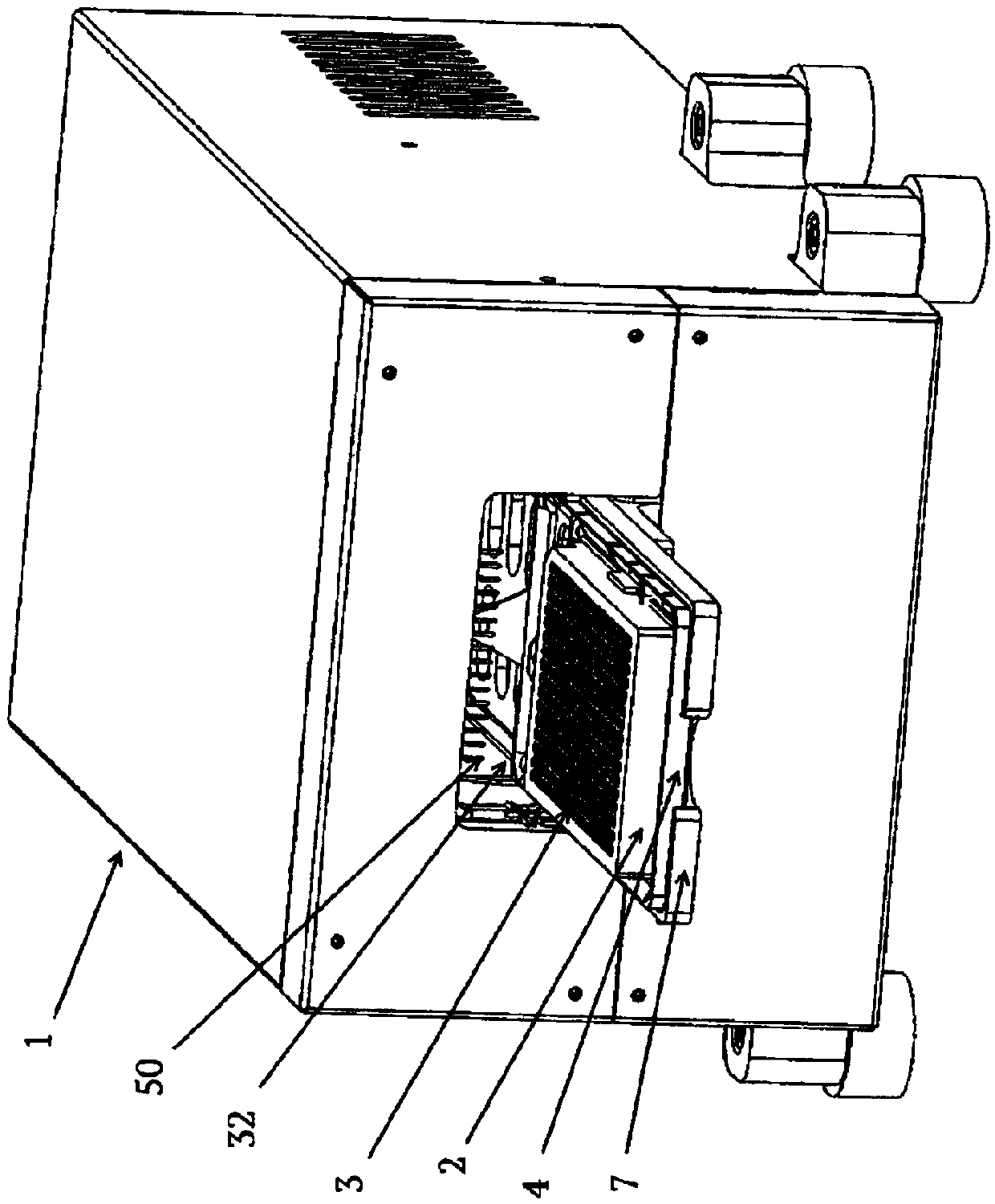
[0092] The first instance of the centrifuge ( Figure 1-Figure 7 ) designed for cleaning and cleaning of the reaction vessel unit. The reaction vessel unit is a microtiter plate 2 . The microtiter plate 2 includes a plurality of reaction vessels 3 arranged in a two-dimensional array. Such microtiter plates typically contain 96, 384 or 1536 reaction volumes3.

[0093] Centrifuge 1 comprises front desk 4, centrifugal part 5 and driving part 6 ( figure 1 ).

[0094] The front desk 4 has a rectangular form in plan view slightly larger than a standard microtiter plate. The outer edge 7 is provided on all side edges of the front desk 4 except for one outer edge adjacent to the eccentric portion 5 .

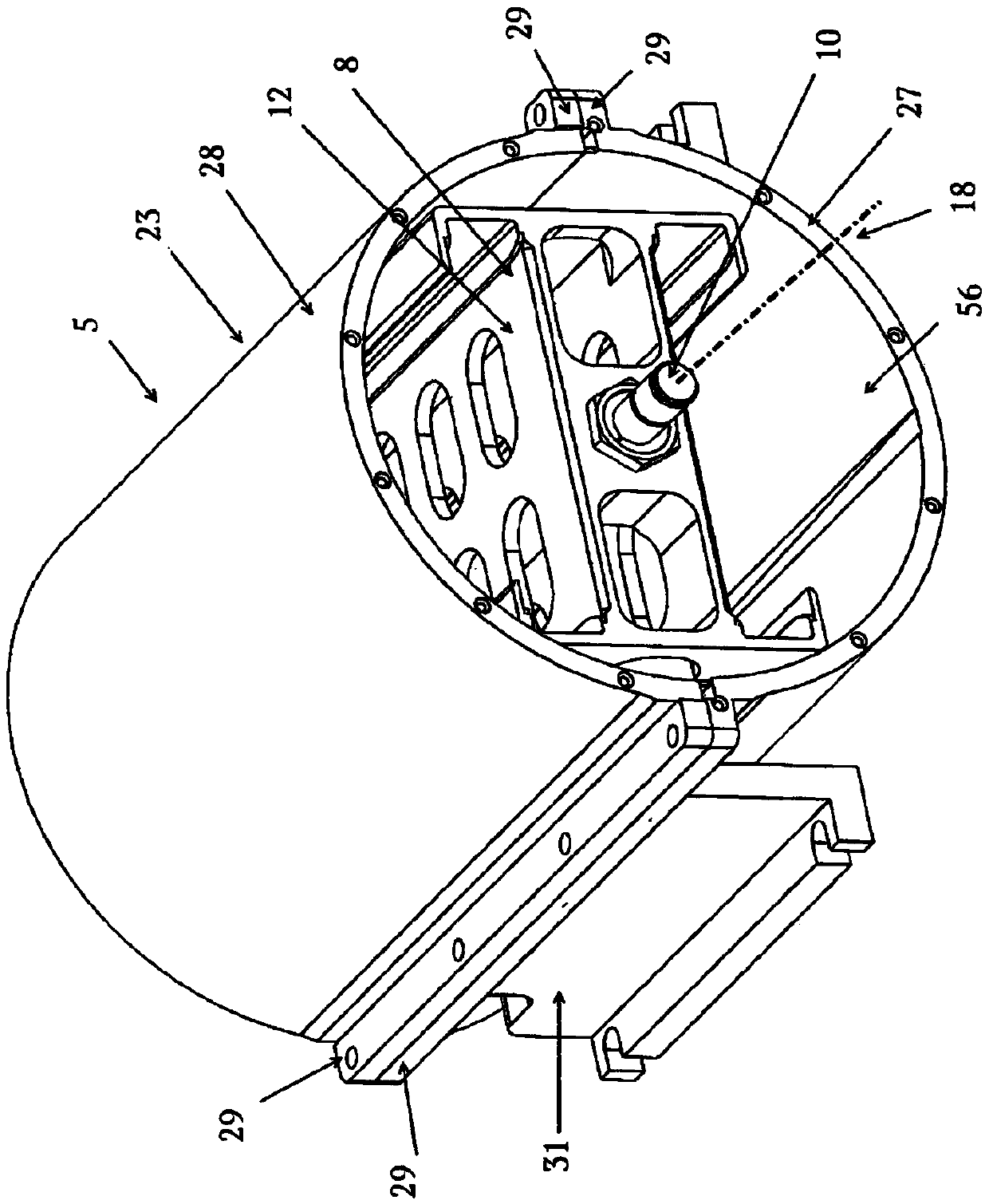
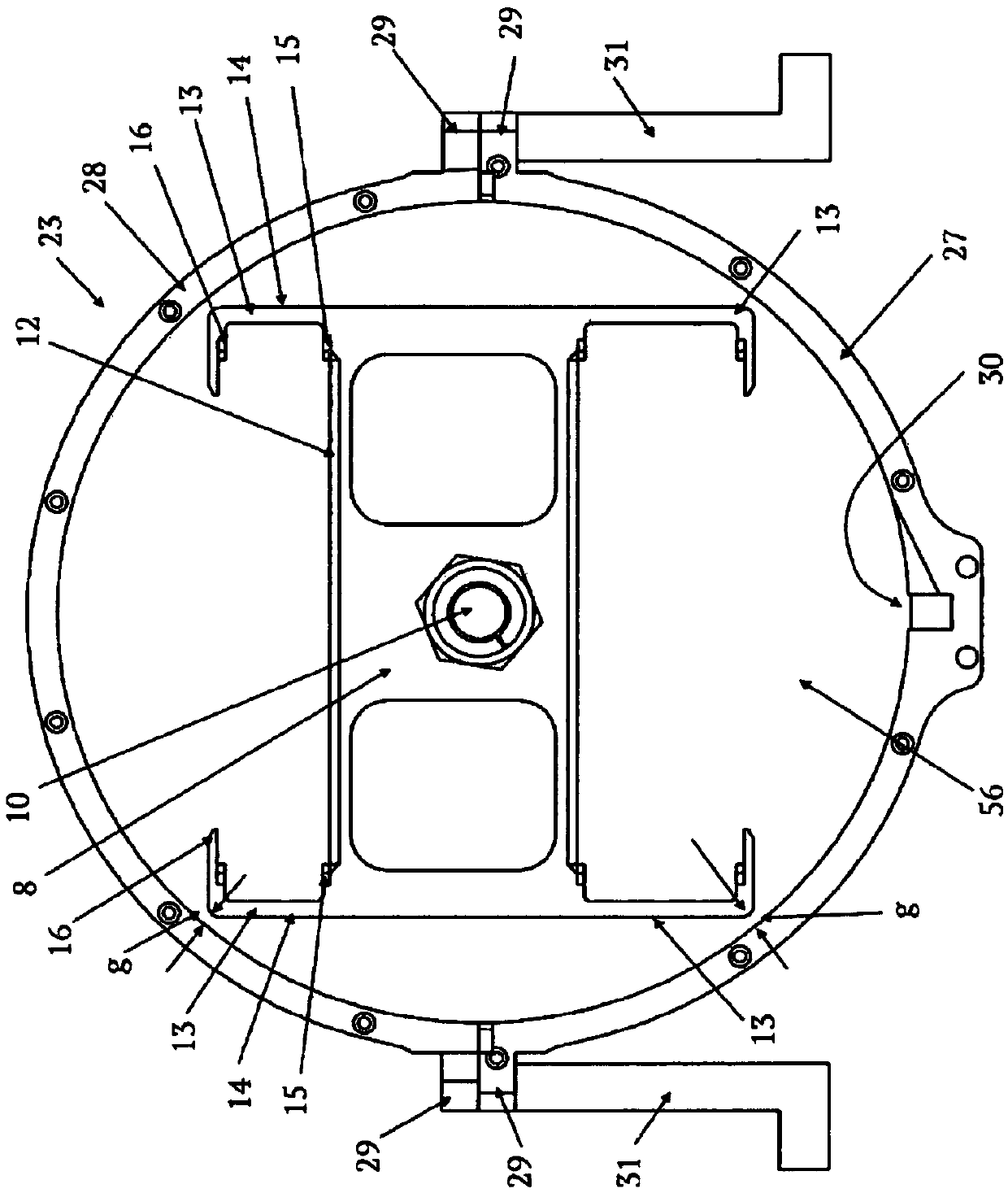
[0095] The centrifugal part 5 includes a rotor 8 and a housing 9 . The rotor 8 is installed on the horizontal shaft 10 ( figure 2 , image 3 ). The rotor 8 comprises two receiving parts, each for receiving a microtiter plate 2 . The receiving part is implemented as a plate tr...


PUM


Abstract

A centrifuge for cleaning a reaction vessel unit, having a rotor for holding at least one reaction vessel unit with its opening(s) directed outwardly, a motor for rotating the rotor around a rotation axis, a housing having a substantially cylindrical inner surface, wherein a drain is provided for discharging fluid expelled from the reaction vessel unit, wherein a gap is provided between the inner surface and the rotor so that by rotating the rotor a wind is generated which drives the expelled fluid on the inner surface to the drain wherein an aspiration pump is connected to the drain for discharging fluid.

Description

technical field [0001] The present invention relates to a centrifuge and method for subjecting a reaction vessel unit to centrifugal force. Background technique [0002] US2009 / 0181359A1 discloses an autoimmune process with high throughput and high sensitivity. As is typical for immunization, a first specific binding member may interact with a second specific binding member to form a complex, wherein the concentration or amount of the complex is defined. This process uses magnetic particles that are immobilized by one of the specific binding members. An important step in automated processing is washing the complexes associated with the magnetic particles. Washing steps have a high impact on throughput sensitivity, specificity, and overall process cost. The fewer cleaning steps required, the faster the process. The better the separation of complexes from non-specifically bound parts, the better the sensitivity of the process. [0003] US 8,329,475 B2 discloses a cleaning...

Claims


Application Information

Patent Timeline
Patent Type & Authority Applications(China)
IPC IPC(8): B01L99/00B08B3/10B08B9/00B04B5/04G01N35/00G01N35/04B04B11/04G01N33/80G01N35/02B01L3/02B03C1/28G01N33/543
CPCB08B3/10B08B9/00B04B5/0407B04B5/0414G01N35/028B01L2300/0829B01L2400/0409B04B2011/046G01N33/54366B03C1/002B03C1/01B03C1/288B03C1/30B03C2201/18B03C2201/26G01N2035/0437B04B7/04B04B15/02B01L13/02B01L3/5085B01L9/523G01N33/54326B04B5/00B08B3/02B08B3/04B08B3/06
Inventor 沃尔夫冈·曼王兆强
Owner YANTAI AUSBIO LAB
Why Eureka
Try Eureka