Centrifugal type blower unit

a centrifugal type, blower technology, applied in the direction of liquid fuel engines, marine propulsion, vessel construction, etc., can solve the problems of interference between the sub-flow air and the main-flow air, the second noise cannot be sufficiently reduced, and the end side of the blade may generate unstable whirls

Inactive Publication Date: 2001-10-09
DENSO CORP
View PDF9 Cites 89 Cited by
  • Summary
  • Abstract
  • Description
  • Claims
  • Application Information

AI Technical Summary

Problems solved by technology

However, the second noise cannot be sufficiently reduced by using the method for reducing the first noise.
Therefore, when the sub-flow air is mixed into the main-flow air, unstable whirl may be generated at the end side of the blades.
That is, an interference between the sub-flow air and the main-flow air is caused, and the second noise is caused.
Thus, the second noise may be generated even though the filter is not provided at the air suction port.

Method used


Image

  • Centrifugal type blower unit
  • Centrifugal type blower unit
  • Centrifugal type blower unit

Examples


first embodiment

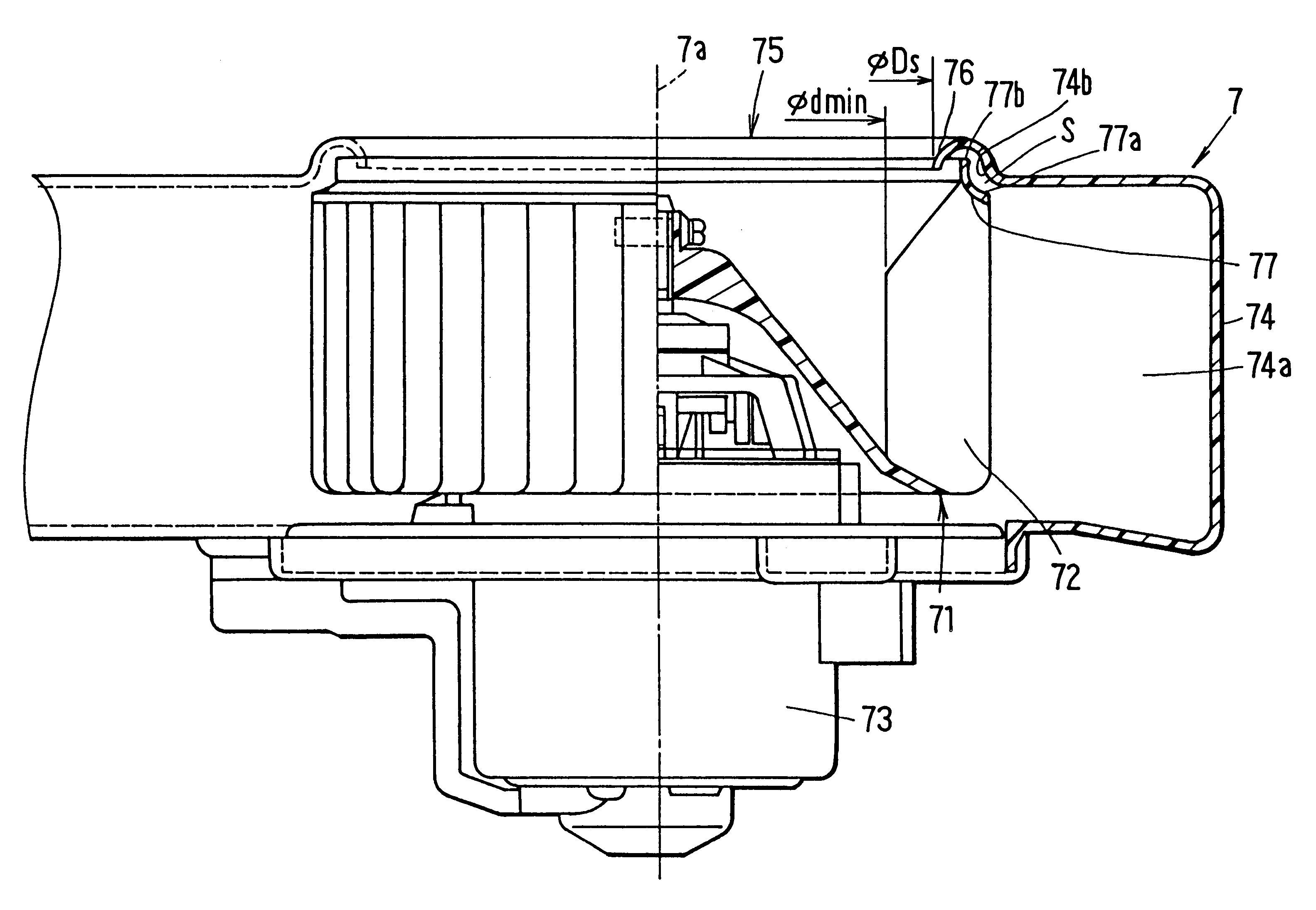
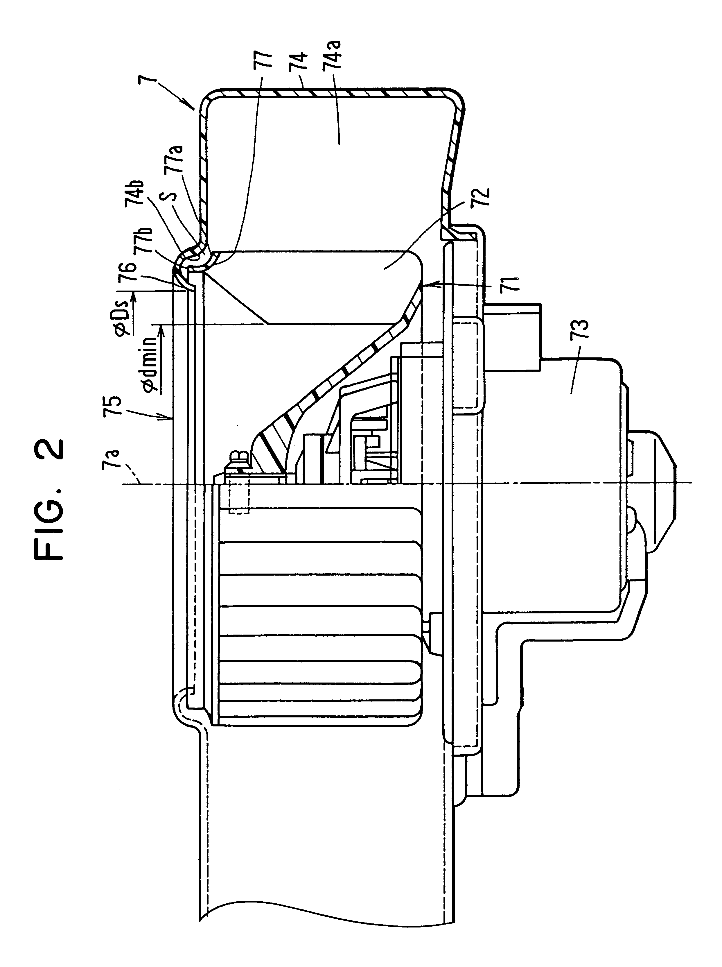
In the first embodiment, as shown in FIG. 4, a shroud 77 is formed integrally with each of the blades 72 using resin. The shroud 77 has a shrouded surface 77a which is opposite to an inner wall 74b of the scroll casing 74 to have a clearance S between the inner wall 74b and the shrouded surface 77a. The shroud 77 is formed approximately into a circular arc shape in cross section along a flow line of main flow of air passing through between the blades 72, so that a sectional area of an air passage within the centrifugal fan 71 is reduced from a radius inner side toward a radius outer side by the shroud 77. That is, at the position where the shroud 77 is formed, a height of each blade 72 is gradually reduced toward the radius outside, as shown in FIG. 4.

Further, the shroud 77 has an extending portion 77b extending from each end of the blades 72 at the side of the air suction port 75 to the air suction side in the axial direction of the rotation axis 7a. The bell-mouth portion 76 exten...

third embodiment

FIG. 9 shows the relationship between the slanting angle .theta. of the slanting portion 72a of the blades 72 and the second noise level, and FIG. 10 shows the relationship between slanting angle .theta. of the slanting portion 72a and the low-frequency noise level. As shown in FIG. 9, when the slanting angle .theta. of the slanting portion 72a is increased to be larger than 30.degree., the second noise can be reduced. However, as shown in FIG. 10, the low-frequency noise is increased as the slanting angle .theta. increases. Thus, according to the present invention, the slanting angle .theta. is set in a range of 30.degree.-70.degree. (i.e., 30.degree..ltoreq..theta..ltoreq.70.degree. ), thereby reducing both of the second noise and the low-frequency noise.

fourth embodiment

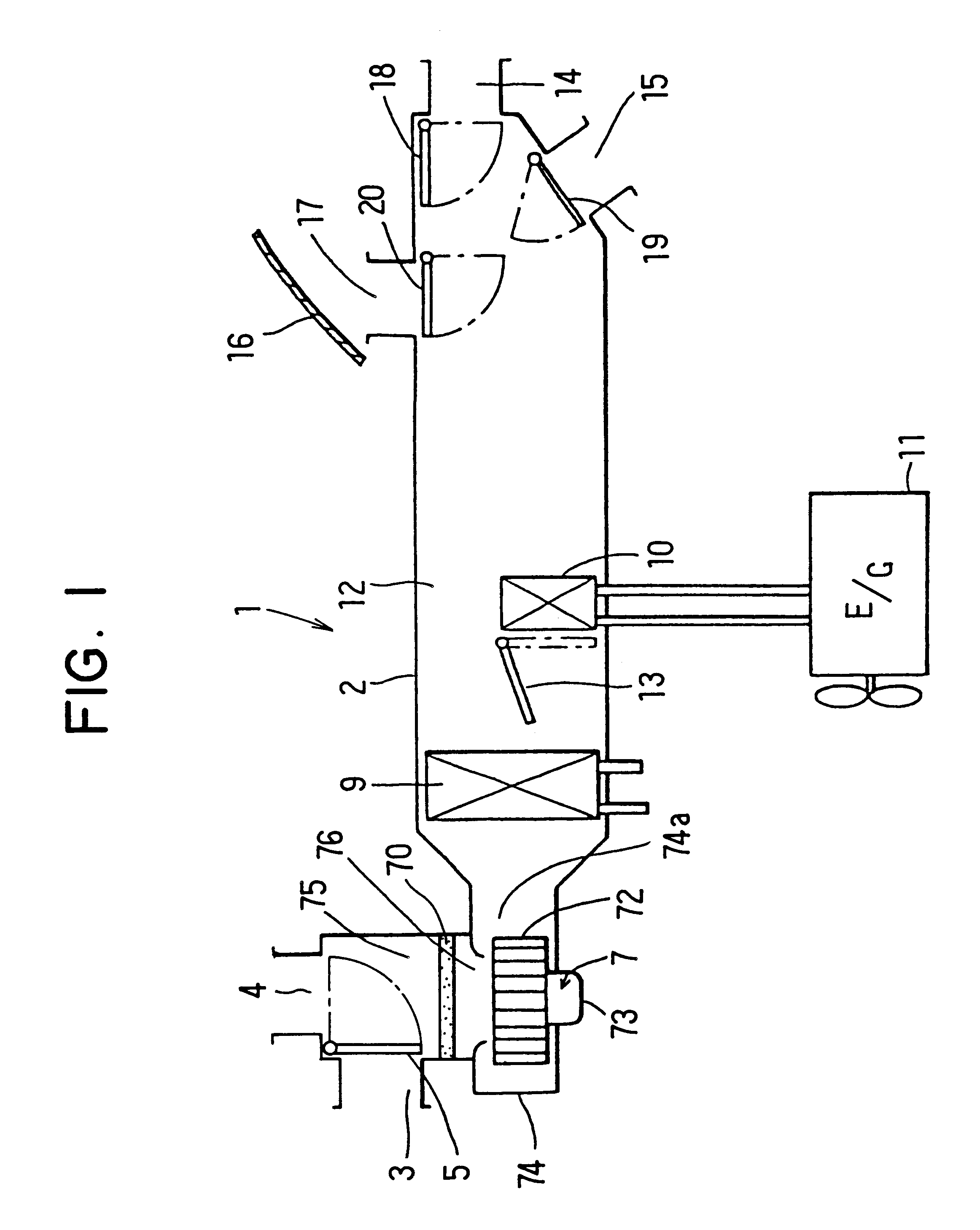
A fourth preferred embodiment of the present invention will be now described FIGS. 11-16. In the present invention, the blower unit 7 is provided to reduce a low-frequency noise about 100-200 Hz while reducing consumption power.

In the fourth embodiment, the slanting portion 72a is formed in the blades 72 similarly to the first embodiment, and each of the blades 72 is formed in such a manner that curvature radius R1 from the inner radius end D1 of the centrifugal fan 71 to 1 / 4 L position is smaller than curvature radius R2 from the outer radius end D2 of the centrifugal fan to 3 / 4 L position. Here, "L" is a length subtracting an inner radius of the centrifugal fan 71 from an outer radius thereof. That is, the length L is the length of each blade 72 in the radius direction of the centrifugal fan 71.

In the centrifugal fan 71, the smaller a fan outlet angle .beta.2 is, the larger the resistance applied to the blades 72 is. Therefore, consumption power of the electrical motor 73 for driv...


PUM


Abstract

In a centrifugal type blower unit, a diameter of an air suction port is set to be larger than a minimum inner diameter of a centrifugal fan, and a slanting portion is formed in each blade of the centrifugal fan at a side of the air suction port so that an inner radius dimension of the centrifugal fan is increased toward the air suction port. Therefore, it can prevent sub-flow air which is sucked into the centrifugal fan from an end side of the blades in an axial direction from interfering with main-flow air which is sucked into the centrifugal fan from an inner radius side of the blades. Thus, the blower unit can reduce second noise generated therefrom without greatly reducing air-blowing capacity.

Description

This application relates to and claims priority from Japanese Patent Application No. Hei. 10-99364 filed on Apr. 10, 1998, and No. Hei. 11-24093 filed on Feb. 1, 1999, the contents of which are hereby incorporated by reference.1. Field of the InventionThe present invention relates to a centrifugal type blower unit which reduces noise generated therefrom without greatly reducing air-blowing capacity. The blower unit is suitable for a vehicle air conditioner.2. Description of Related ArtIn a conventional blower unit, noise (hereinafter referred to as "first noise") may be generated when air blown from a centrifugal fan collides with a nose portion of a scroll casing. The first noise is approximately proportional to a rotation speed of the centrifugal fan and number of blades of the centrifugal fan. Therefore, in the conventional blower unit, the shape of the nose portion is suitably formed so that the first noise can be decreased.However, according to an experiment of the inventors of...

Claims


Application Information

Patent Timeline
Patent Type & Authority Patents(United States)
IPC IPC(8): F04D29/00F04D29/66F04D29/16F04D29/08F04D29/70
CPCF04D29/162F04D29/661F04D29/703
Inventor MATSUNAGA, KOUJIKAMEOKA, TERUHIKOITO, KOJITANAKA, TOHRUMITSUISHI, YASUSHI
Owner DENSO CORP
Why Eureka
Try Eureka