Centrifugal blood pump apparatus

a centrifugal and pumping technology, applied in the direction of piston pumps, positive displacement liquid engines, therapy, etc., can solve the problems of difficult to compact the centrifugal blood pump apparatus, hemolysis occurs,

Active Publication Date: 2008-12-30
TC1 LLC
View PDF12 Cites 84 Cited by
  • Summary
  • Abstract
  • Description
  • Claims
  • Application Information

AI Technical Summary

Problems solved by technology

During the rotation of the impeller made only by the action of the hydrodynamic pressure groove, there is a fear that hemolysis occurs when the impeller has a small number of rotations.
Thus it is very difficult to make the centrifugal blood pump apparatus compact.

Method used


Image

  • Centrifugal blood pump apparatus
  • Centrifugal blood pump apparatus
  • Centrifugal blood pump apparatus

Examples


Embodiment Construction

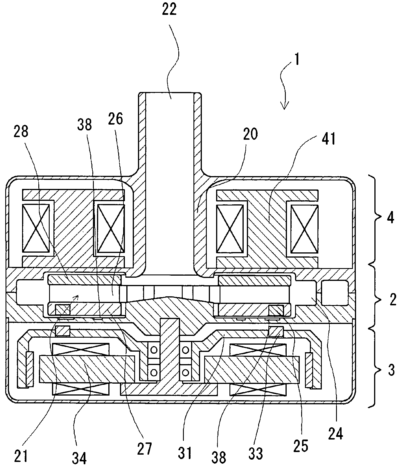
[0027]An embodiment of the centrifugal blood pump apparatus according to the present invention is described below with reference to FIGS. 1 through 11.

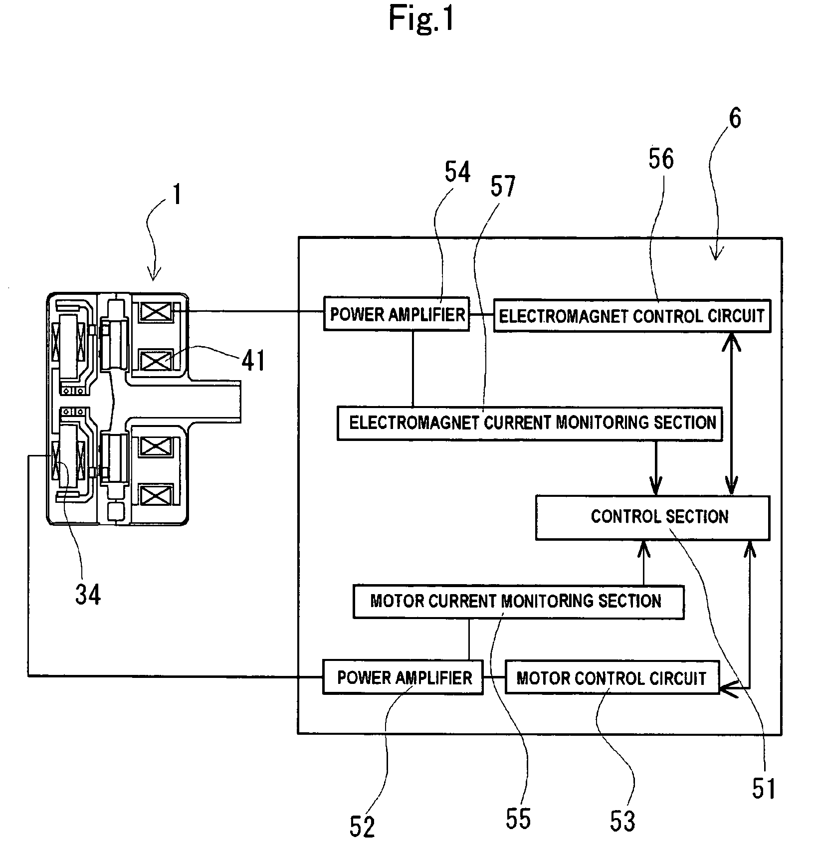
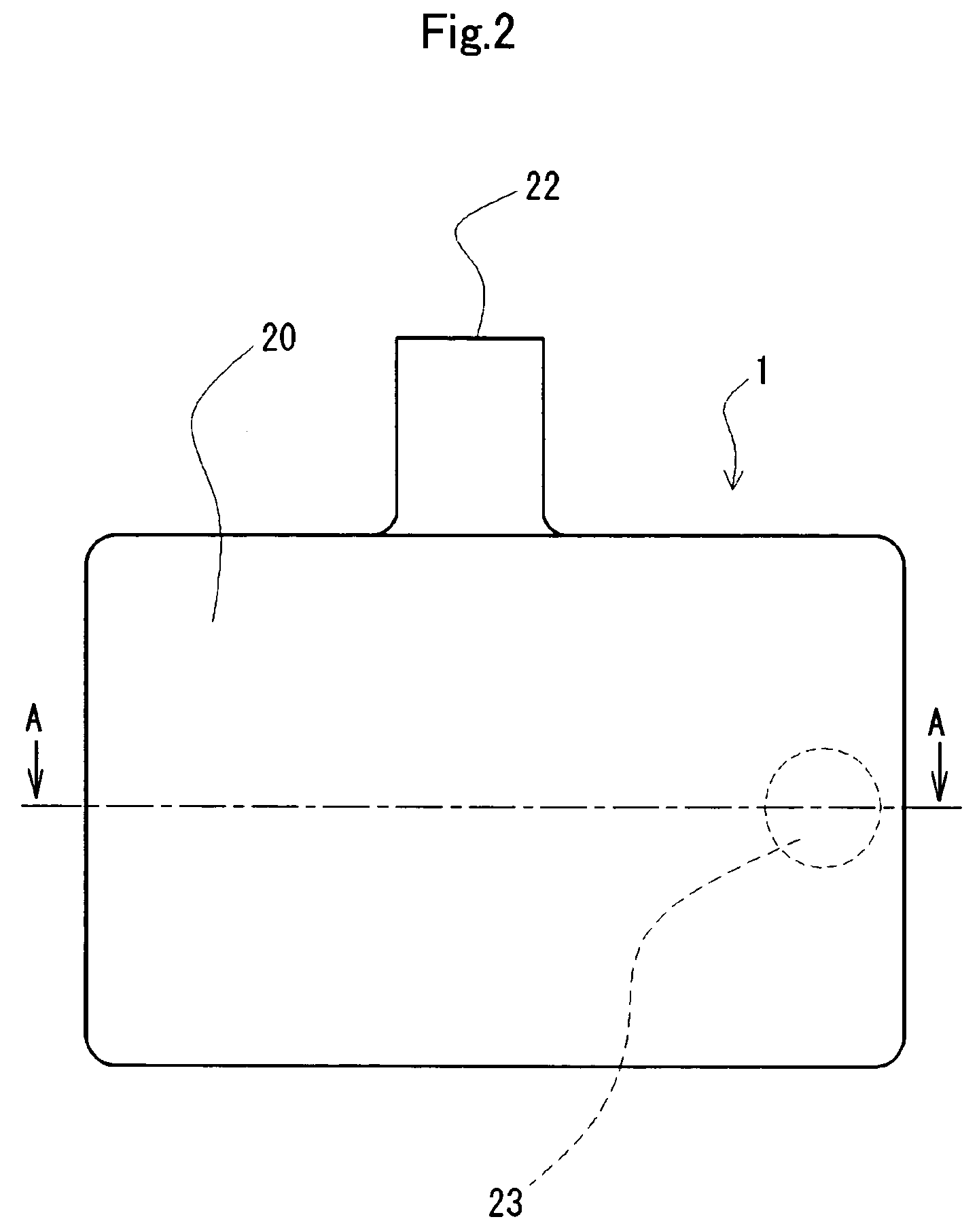
[0028]A centrifugal blood pump apparatus 1 of the present invention has a housing 20 having a fluid inlet port 22 and a fluid outlet port 23, a centrifugal pump section 2 including an impeller 21 having a first magnetic material 25 therein and rotating inside the housing 20 to feed a fluid by a centrifugal force generated during a rotation thereof, an impeller rotational torque generation section 3 for attracting and rotating said impeller, and a hydrodynamic pressure groove 38 formed at a portion of an inner surface of the housing 20 at a rotor-disposed side or at a portion of a surface of the impeller 21 at the rotor-disposed side. The impeller 21 rotates without contacting the housing 20 owing to an action of the hydrodynamic groove 38. The centrifugal blood pump apparatus 1 further includes an electromagnet 41 for attracting the f...


PUM


Abstract

A centrifugal blood pump apparatus has a centrifugal pump section including an impeller having a first magnetic material therein and rotating inside the housing to feed a fluid by a centrifugal force generated during a rotation thereof; an impeller rotational torque generation section having a rotor having a magnet for attracting the first magnetic material of the impeller thereto, and a motor for rotating the rotor; and a dynamic pressure groove formed at a portion, of an inner surface of the housing, located at a rotor-disposed side thereof. The centrifugal blood pump apparatus further includes an electromagnet for attracting the impeller in a direction opposite to a direction in which the magnet of the rotor attracts the impeller and helping the impeller levitate.

Description

BACKGROUND OF THE PRESENT INVENTION[0001]The present invention relates to a centrifugal blood pump apparatus for pumping a medical fluid, typically blood.[0002]In recent medical treatment, centrifugal blood pumps are increasingly used in artificial heart / lung units for extracorporeal blood circulation. Centrifugal pumps of the magnetic levitation type wherein a driving torque from an external motor is transmitted to an impeller through magnetic coupling are commonly used because the physical communication between the blood chamber of the pump and the exterior can be completely excluded and invasion of bacteria can be prevented.[0003]The present applicant proposed a centrifugal blood pump disclosed in U.S. Pat. No. 5,947,703.[0004]The centrifugal blood pump includes the housing having the inlet port and the outlet port for blood and adapted to receive blood therein, and the impeller adapted to rotate within the housing for feeding blood by a centrifugal force developed during rotatio...

Claims


Application Information

Patent Timeline
Patent Type & Authority Patents(United States)
IPC IPC(8): A61M37/00F04B17/00A61M1/00A61M60/109A61M60/205A61M60/232A61M60/419
CPCA61M1/101A61M60/205A61M60/419A61M60/422A61M60/232A61M60/109
Inventor MORI, TAKEHISAYAEGASHI, MITSUTOSHIOZAKI, TAKAYOSHI
Owner TC1 LLC
Why Eureka
Try Eureka